Puncher

A perforating device and a technology of a rotary drive mechanism, which is applied in metal processing and other directions, can solve the problems of time-consuming and laborious wiring operations, hindering perforation operations, and difficulty in seeing, etc., and achieve the effect of reducing the number of wiring, shortening the time of wiring operations, and improving the efficiency of perforation

Inactive Publication Date: 2007-02-21
DAIDO KOGYO CO LTD
View PDF1 Cites 4 Cited by
  • Summary
  • Abstract
  • Description
  • Claims
  • Application Information

AI Technical Summary

Problems solved by technology

Moreover, since there are two motors, it is necessary to configure multiple power lines, etc.
For these reasons, the wiring work during the assembly of the conventional punching device 110 is time-consuming and laborious.
[0009] In addition, in the conventional piercing device 110, since the punch rotation drive motor 151 is provided in front of the punch support body 132

Method used


Image

  • Puncher
  • Puncher
  • Puncher

Examples


Embodiment Construction

[0048] Hereinafter, the punching device according to the embodiment of the present invention will be described based on the drawings. The perforating device uses a rotating punch to make holes in the perforated materials such as sheets, sheet bundles, wooden boards, metal foils, and metal plates.

[0049] (Composition description)

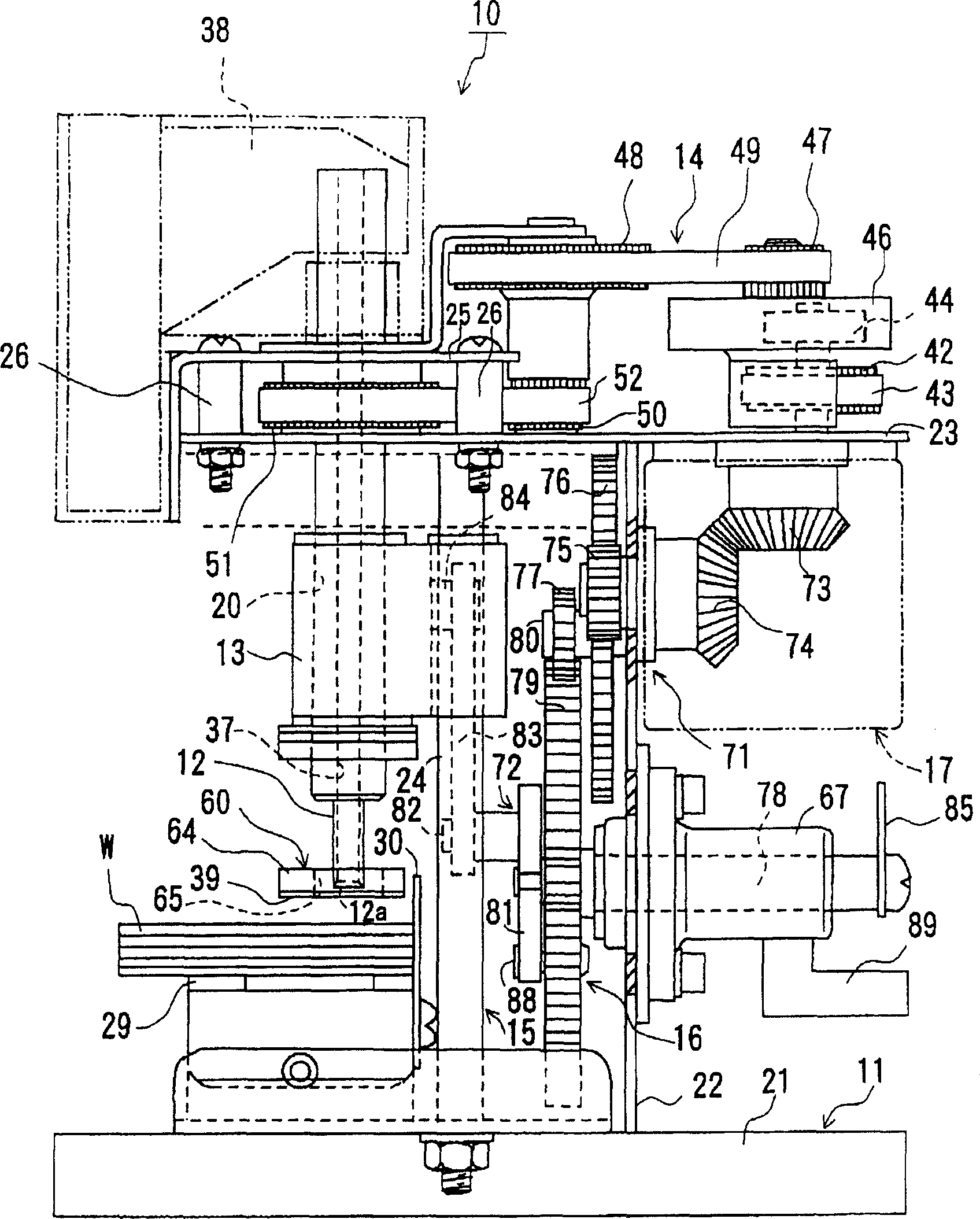
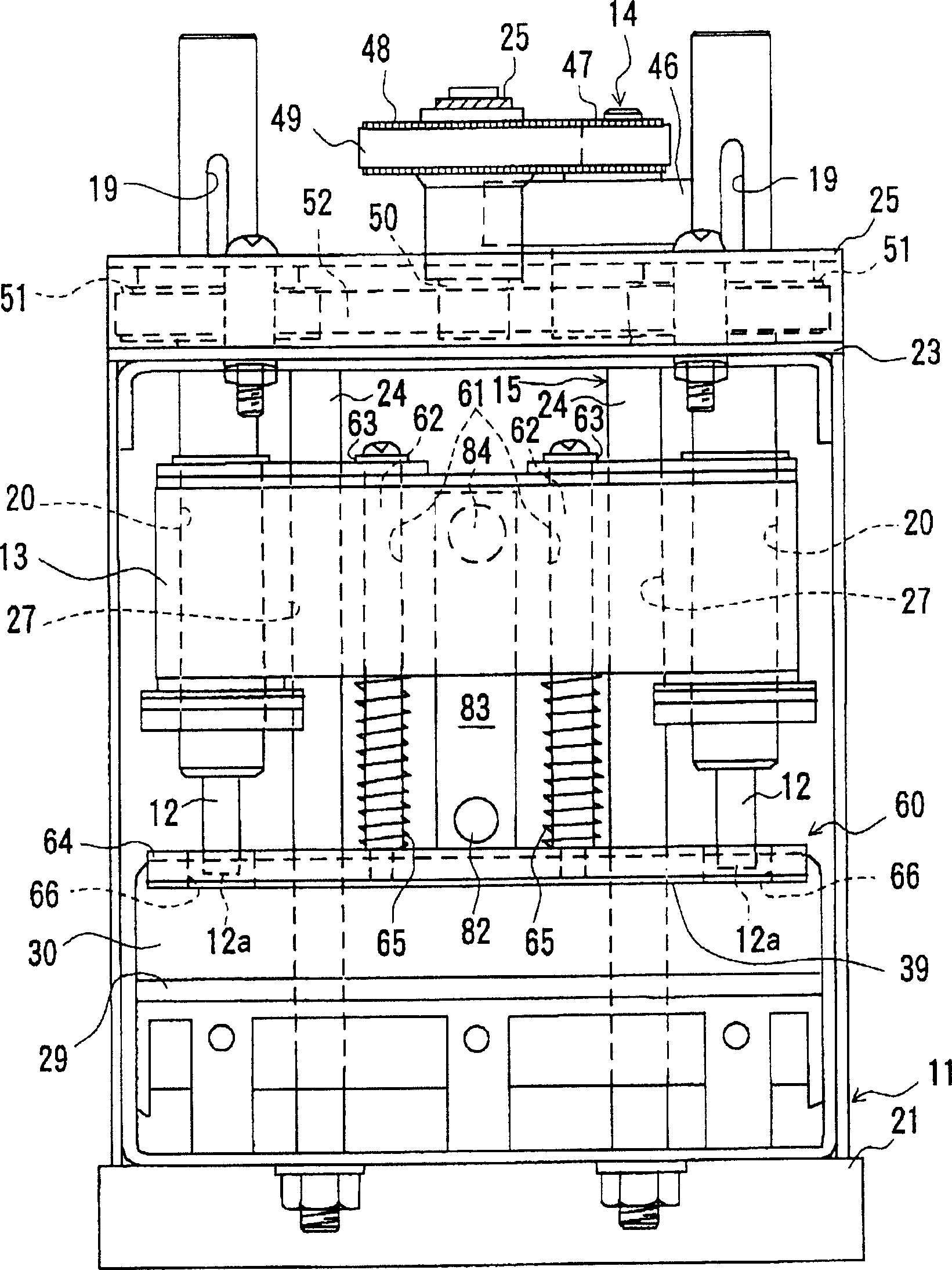
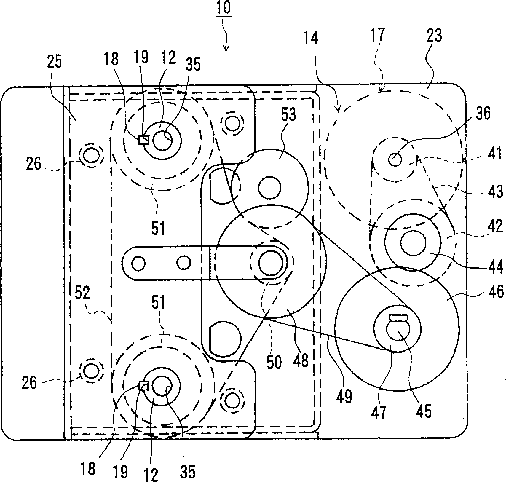
[0050] Such as Figure 1 to Figure 6 The punching device 10 shown has: a device body 11; a punch 12 that makes a hole in the material W to be punched; a lifting body (punch support) 13 that supports the punch 12 to rotate freely and cannot move axially; The rotary drive mechanism 14 for the rotation of the head 12; the reciprocating support mechanism 15 that supports the lifting body 13 freely reciprocating on the device body 11; the reciprocating drive mechanism 16 that makes the lifting body 13 reciprocate; the setting to make the reciprocating drive mechanism 16 move The motor 17 and the like in the main body 11 of the device. The piercing device 10...


PUM


Abstract

A perforator is composed of a punch head for perforating on a material, a rotation driver for making said punch head to rotate, a reciprocating driver for making said punch heat to move axially, and a motor for driving said both drivers.

Description

Technical field [0001] The present invention relates to a punching device that allows a punch to rotate and move to make holes on materials to be punched, such as sheets, sheet bundles, metal foils, and thin plates. Background technique [0002] Conventionally, among the punching devices, there is a type of punching device in which a punch rotates and a hole is made in the material to be punched (refer to Citation 1). This type of perforation device 110 (refer to Figure 7 , Figure 8 The punch 111 of) is rotatably installed on the punch support 132. [0003] In front of the punch support body 132, a punch rotation drive motor 151 for rotating the punch 111 is provided. The rotational force of the punch rotation driving motor 151 passes through the toothed drive pulley 153 provided on the output shaft 152 of the motor 151; the toothed pulley 154 provided on the punch 111; The toothed belts 155 of the wheels 153 and 154 are transferred to the punch 111. [0004] In addition, the p...

Claims


Application Information

Patent Timeline
IPC IPC(8): B26F1/02
Inventor 西村和夫池田宪一郎
Owner DAIDO KOGYO CO LTD
Why Eureka
Try Eureka