
High speed free-space optical communications

A free-space, optical communication technology, used in multiplexing communication, optical multiplexing systems, electrical components, etc., can solve the problems of lack, inability to achieve tolerance power and limit alignment, and reduce the amount of wiring. , the effect of reducing complexity and maintenance costs

Active Publication Date: 2014-12-03
朗美通经营有限责任公司
View PDF5 Cites 4 Cited by
  • Summary
  • Abstract
  • Description
  • Claims
  • Application Information

AI Technical Summary

Problems solved by technology

Likewise, single VCSEL devices are best suited for bandwidth and cost structures, but lack the power and margin alignment necessary to approach unachievable margins

Method used


Image

  • High speed free-space optical communications
  • High speed free-space optical communications
  • High speed free-space optical communications

Examples


Embodiment Construction

[0017] array cluster

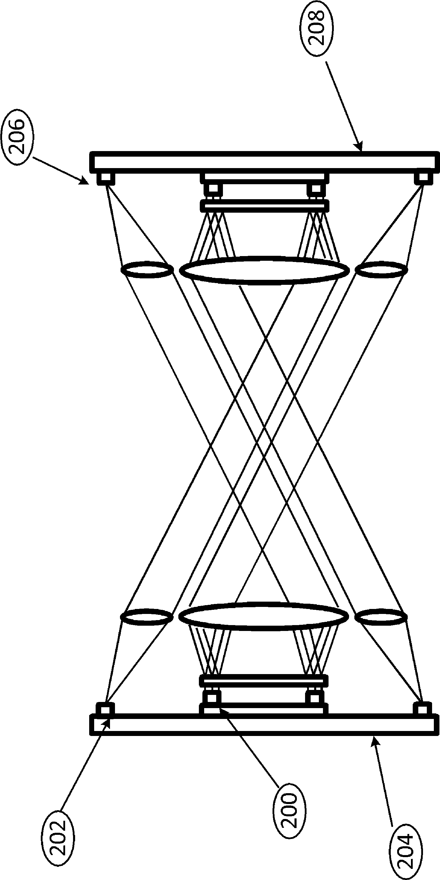
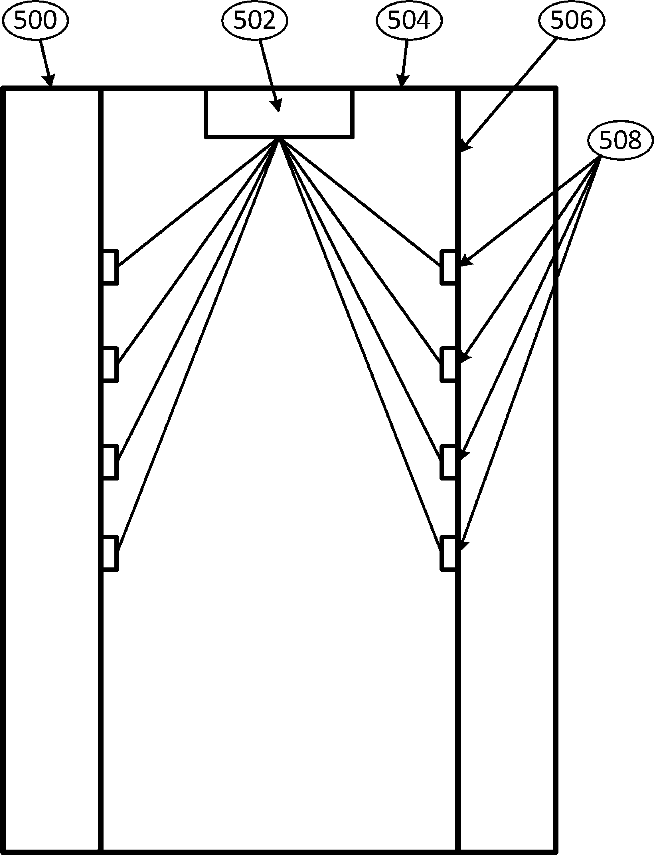
[0018] An embodiment is disclosed comprising a single, dual, 1D or 2D array of small clusters of high power and high speed free space laser beams such as those described in a related application, which arrive in a symmetrical manner on the receiving side for detection on a corresponding array of devices so as to facilitate a mutual pair of inwardly facing devices to provide sufficient two-way communication. Clusters can be wired in parallel, or can be broken down into binary-weighted subgroups driven individually and in parallel. In either case, the beams from each individual cluster can be mixed using a holographic optical diffusing element that spreads the beams to a collimating lens for delivery to the collecting lens of each corresponding detector. This also facilitates board-to-board "daisy chaining" schemes to enable a bus-like data architecture shared by all boards.

[0019] figure 1 depicts from figure 2 system in , or any single channel tra...


PUM


Abstract

High power, high speed VCSEL arrays are employed in unique configurations of arrays and sub-arrays. Placement of a VCSEL array behind a lens allows spatial separation and directivity. Diffusion may be employed to increase alignment tolerance. Intensity modulation may be performed by operating groups of VCSEL emitters at maximum bias. Optical communications networks with high bandwidth may employ angular, spatial, and / or wavelength multiplexing. A variety of network topologies and bandwidths suitable for the data center may be implemented. Eye safe networks may employ VCSEL emitters may be paired with optical elements to reduce optical power density to eye safe levels.

Description

[0001] Cross References to Related Applications [0002] This application claims priority to US Provisional Patent Application No. 61 / 528,119, filed August 26, 2011, and Provisional Application No. 61 / 671,036, filed July 12, 2012, each of which is incorporated herein by reference in its entirety. Background technique [0003] The bandwidth at which data can be transmitted, and the range over which that data can be conveyed outdoors, has been dependent on technologies involving slower single or arrayed high-power semiconductor laser transmitters or combinations of such transmitters with optical modulators and / or optical amplifiers, Or by using multiple wavelengths in combination with the aforementioned components to achieve high bandwidth rates for free-space optical communication over distances beyond a few meters. To date, the complexity involved in implementing these technologies has become prohibitively costly, especially for the short distances measured in meters for local...

Claims


Application Information

Patent Timeline
Patent Type & Authority Applications(China)
IPC IPC(8): H04J14/00
CPCH04B10/1143H04B10/803
Inventor 约翰·R·约瑟夫凯文·L·利尔戴维·阿贝尔
Owner 朗美通经营有限责任公司
Learn More