Head substrate and thermal head substrate

A head substrate and driver technology, applied in printing and other directions, can solve problems such as the difficulty of miniaturization and cost reduction of thermal heads

Active Publication Date: 2009-09-09
SEIKO EPSON CORP
View PDF3 Cites 3 Cited by
  • Summary
  • Abstract
  • Description
  • Claims
  • Application Information

AI Technical Summary

Problems solved by technology

That is, there are problems such as miniaturization of the thermal head and difficulty in cost reduction accompanying the miniaturization.
As one of the solutions, there is the scheme disclosed in Patent Document 3, but at this time, the clock signal line and the latch signal line are arranged in the mounting area of ​​the driver IC, and there is an influence of the high-frequency clock signal on other signal lines, especially for The output line of the head drive signal is affected by noise, which becomes the main cause of errors

Method used


Image

  • Head substrate and thermal head substrate
  • Head substrate and thermal head substrate
  • Head substrate and thermal head substrate

Examples


no. 1 Embodiment approach

[0045] (about thermal head)

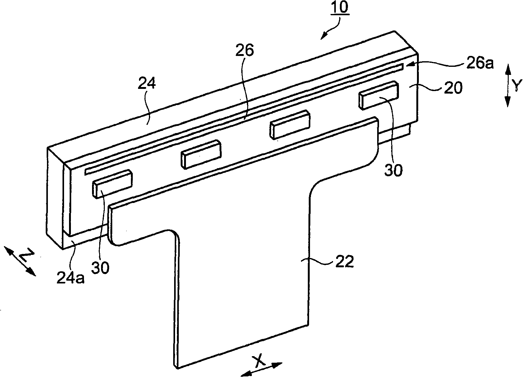
[0046] Regarding the thermal head of the first embodiment, reference will be made to figure 1 illustrate. figure 1 It is a perspective view of the appearance of the thermal head. in, figure 1 The X direction shown indicates the width direction of the thermal paper to be printed when the thermal head is used in a thermal printer, the Y direction indicates the paper conveying direction of the thermal paper in the thermal head, and the Z direction indicates the same direction as the X direction and the Y direction. vertical direction.

[0047] Such as figure 1 As shown, the thermal head 10 includes: a thermal head substrate 20 , a driver IC 30 , an FPC 22 and a heat sink 24 . The thermal head substrate 20 is made of an insulating material and formed in a long rectangular plate shape, and a heating element row 26a composed of a plurality of heating elements 26 is formed near the end of one long side. The driver IC 30 constitutes a control circui...

no. 2 Embodiment approach

[0097] Here, refer to Figure 7 and Figure 8 The thermal head substrate of the second embodiment will be described. Figure 7 It is a pattern pattern diagram of the thermal head board|substrate of 2nd Embodiment. Figure 8 It is a part of the input-output terminal seen from the input-output terminal side of the driver IC of the second embodiment. In addition, about the same structure and content as 1st Embodiment, the same code|symbol is attached|subjected, and the description is abbreviate|omitted.

[0098] Such as Figure 7 As shown, the thermal head substrate 20A is mounted with a driver IC 30A (refer to Figure 8 ) IC mounting part 31, on the heating element R1 ~ R512 side, from Figure 7 Starting from the right side of the center, it is arranged in a row (the first pad column) in sequence: the first latch pad LAT1, the logic power supply pad VDD, the signal output pad SO, and the output pads that conduct with 128 heating elements 26. The pads DO1 to DO128, the sign...

no. 3 Embodiment approach

[0112] Regarding the thermal head substrate of the third embodiment, refer to Fig. 9 (a), Fig. 9 (b) and Figure 10 to illustrate.

[0113] FIG. 9( a ) shows a pattern layout diagram related to the IC mounting portions 31 c and 31 d , and FIG. 9( b ) shows a pattern layout diagram related to the IC mounting portions 31 a and 31 b. Figure 10 It is a figure which shows a part of the input-output terminal of the driver IC of 3rd Embodiment, Specifically, it is a figure seen from the input-output terminal side. In addition, about the same structure and content as 2nd Embodiment, the same code|symbol is attached|subjected, and the description is abbreviate|omitted.

[0114] As shown in Fig. 9 (a) and Fig. 9 (b), the thermal head substrate 20B is equipped with a driver IC 30B (refer to Figure 10 ) in the IC mounting portion 31, on the side of the heating elements R1 to R512, from the right in FIG. The pad SO, the first latch pad LAT1 , the output pads DO1 to DO128 electrically ...


PUM


Abstract

The invention provides a head substrate equipped with a driver IC which selectively drives a plurality of driving elements. A plurality of external connection terminals comprise a plurality of joints for receiving clock signals and logic power used for the driver IC. A first welding disk array comprises a plurality of welding disks which form at the side of equipping the driver IC, and the welding disks are connected with the terminals arranged on the driver IC; the first welding disk array comprises grounding welding disks for setting driver IC. An input signal wiring pattern electrically connects the external connection terminals with the welding disks in the first welding disk array and a second welding disk array, and includes a clock signal line for supplying the clock signal (CLK) to the driver IC and a logic power line (VDD) for supplying the logic power to the driver IC. A part of the clock signal line and a part of the logic power line are disposed between the first welding disk array and the second welding disk array.

Description

technical field [0001] The present invention relates to a head substrate provided with a driver IC that selectively drives a plurality of driving elements. Background technique [0002] As one of the electronic devices, a thermal printer is known. A thermal printer has a thermal head in which heating elements are arranged in a straight line. The heating element arranged on the thermal head selectively generates heat by energizing it. And, the heat energy selectively reacts with the color developer contained in the thermal paper to print various information on the thermal paper. This printing method is called thermal color development method. [0003] This thermal head has: a thermal head substrate (substrate) of a long rectangular shape; a plurality of heating elements (heating resistors) arranged along the long side at one end of the long side of the substrate; arranged in parallel with the plurality of heating elements and can be A driver IC that selectively generates ...

Claims


Application Information

Patent Timeline
Patent Type & Authority Applications(China)
IPC IPC(8): B41J2/335B41J2/345
CPCB41J2/04541B41J2/04523B41J2/04581B41J2/0458B41J2/32
Inventor 大泽光平中岛聪
Owner SEIKO EPSON CORP
Why Eureka
Try Eureka