Planar inverted F shaped antenna, and method for adjusting input impedance

An antenna and planar technology, applied in the field of planar inverted F-type antenna and its input impedance adjustment, can solve the problems of increasing the cost of antenna certification and increasing the complexity of molds, etc.

Inactive Publication Date: 2007-02-21
FOXCONN (KUNSHAN) COMPUTER CONNECTOR CO LTD +1
View PDF0 Cites 5 Cited by
  • Summary
  • Abstract
  • Description
  • Claims
  • Application Information

AI Technical Summary

Problems solved by technology

However, this method will increase the complexity of the mold and increase the cost of antenna certification

Method used


Image

  • Planar inverted F shaped antenna, and method for adjusting input impedance
  • Planar inverted F shaped antenna, and method for adjusting input impedance
  • Planar inverted F shaped antenna, and method for adjusting input impedance

Examples


Embodiment Construction

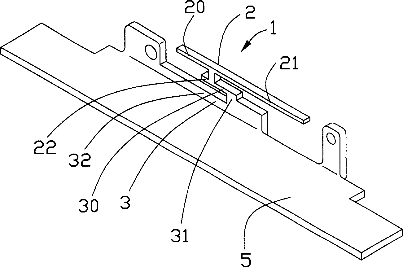
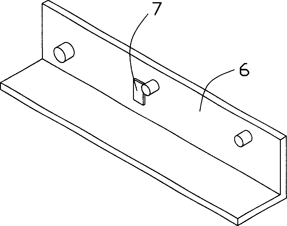
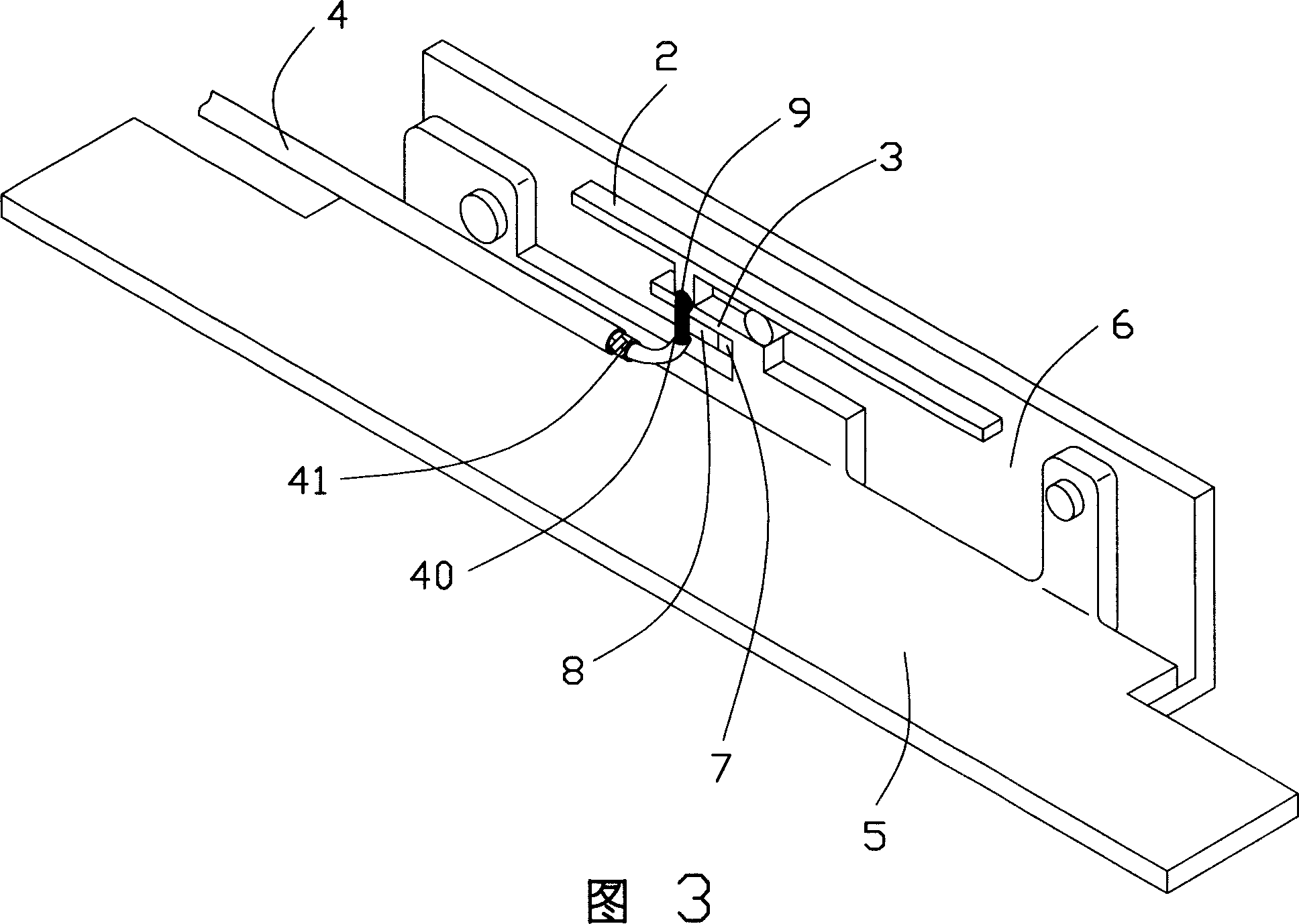
[0015] figure 1 Shown is an existing planar inverted-F antenna 1 used inside a notebook computer. The planar inverted F-shaped antenna 1 is integrally formed by a bracket connecting the liquid crystal display screen inside the notebook computer with the casing or an independent metal sheet with a slot (not labeled). The above-mentioned bracket is a metal sheet. see figure 1 , figure 2 As shown in FIG. 3 , the planar inverted-F antenna 1 includes a radiation part 2 , a ground part 5 , a coaxial cable 4 and an impedance matching part 3 connecting the radiation part 2 and the ground part 5 .

[0016] The radiating part 2 is in the shape of a longitudinal strip, and includes a first radiating unit 20 , a second radiating unit 21 and a third radiating unit 22 that are located in the same longitudinal direction as the first radiating unit 20 and extend toward the other end. The third radiating unit 22 is connected to the intersection of the first radiating unit 20 and the second...


PUM


Abstract

The antenna unit includes antenna prepared from sheet metal, shell body, and coaxial cable. The antenna includes radiation sect, grounding sect, and impedance matching sect with impedance matching space. The coaxial cable includes inner core connected to the radiation sect, and braid conductor connected to the grounding sect. The antenna unit also includes metal foil located inside the impedance matching space. The metal foil connected to the impedance matching sect is in use for adjusting input impedance. The method for adjusting input impedance includes steps: (1) selecting antenna and shell utilized inside notebook computer; (2) sticking metal foil to certain area inside shell; thus, after antenna is assembled to shell, the said area is corresponding to the impedance matching space; (3) assembling antenna to shell to make metal foil contact to the impedance matching sect. Advantages are: without need of change dies for antenna, and reducing cost for authenticating antenna.

Description

【Technical field】 [0001] The invention relates to an antenna, in particular to a planar inverted-F antenna used in electronic equipment and an input impedance adjustment method thereof. 【Background technique】 [0002] With the increasing popularity of products with wireless transmission capabilities, it is very convenient for users to transmit data wirelessly without being restricted by the environment. [0003] Portable electronic devices such as notebook computers often utilize antennas for wireless data transmission. However, the antenna is greatly affected by its environment in the whole system, so the functionality of the antenna with the same structure in different notebook computers will also be greatly affected by the different background conditions. Therefore, in different notebook computers, the antenna design with the same excitation principle must be fine-tuned to have normal functions. [0004] For stamped metal antennas, the traditional correction method is t...

Claims


Application Information

Patent Timeline
Patent Type & Authority Applications(China)
IPC IPC(8): H01Q1/38H01Q13/08
Inventor 戴隆盛谷柏冈王舒嬿
Owner FOXCONN (KUNSHAN) COMPUTER CONNECTOR CO LTD
Why Eureka
Try Eureka