
Novel loop detection and control circuit

A loop detection and control circuit technology, applied in control/regulation systems, electrical components, regulating electrical variables, etc., can solve the problems of only using digital chips for detection and judgment, occupying a large space, and complicated processes, so as to save the cost of material preparation Pressure, the effect of reducing certification costs

Active Publication Date: 2019-12-24
SHENZHEN YUANNENG ELECTRIC CO LTD
View PDF4 Cites 0 Cited by
  • Summary
  • Abstract
  • Description
  • Claims
  • Application Information

AI Technical Summary

Problems solved by technology

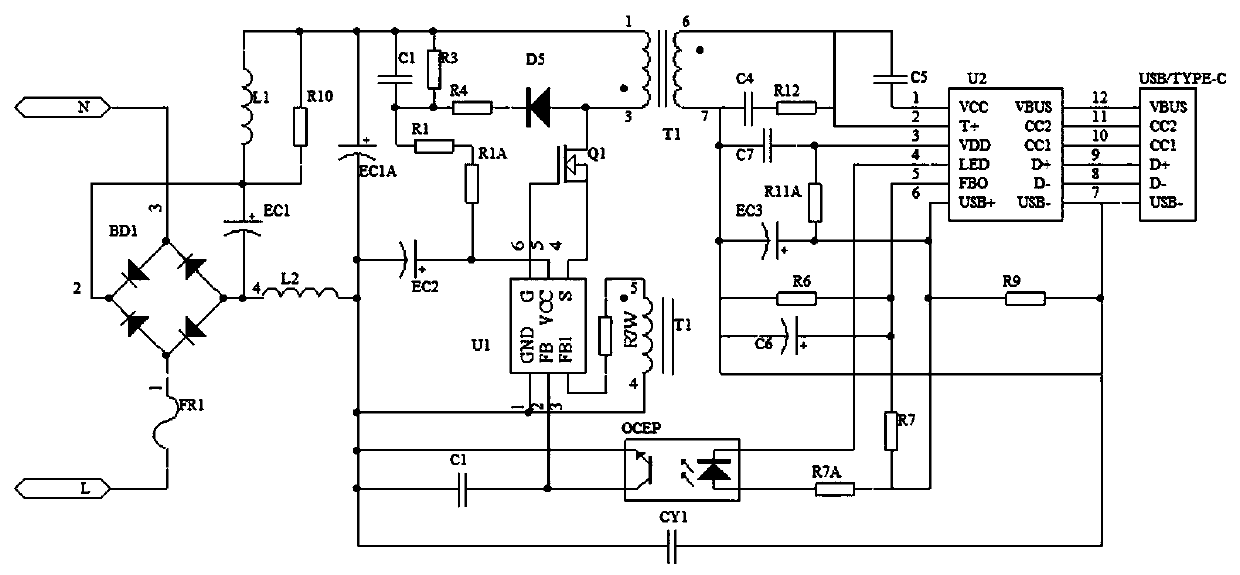
[0008] At present, PSR primary side feedback is used for fast charging, and some Ewatts also use transformer mutual inductance feedback. When square wave detection technology is used to transmit current and voltage signals, it takes a long time to transmit the voltage and current signals to the primary. After the primary receives the signal, it readjusts. FB foot reference constant pressure and CS foot current reference, time delay, usually need several MS or even dozens of MS, and the detection and judgment are complicated and only digital chips can be used, which is costly; in addition, PI also uses mutual inductance feedback, but it is not directly in In the transformer, the process is more complicated, and it straddles the primary pole, taking up a lot of space
And these two are powered by auxiliary windings, resulting in the need for additional voltage regulation on VCC

Method used


Image

  • Novel loop detection and control circuit
  • Novel loop detection and control circuit
  • Novel loop detection and control circuit

Examples


Embodiment Construction

[0042] Embodiments of the present invention are described in detail below, examples of which are shown in the drawings, wherein the same or similar reference numerals designate the same or similar elements or elements having the same or similar functions throughout. The embodiments described below by referring to the figures are exemplary and are intended to explain the present invention and should not be construed as limiting the present invention.

[0043] In describing the present invention, it should be understood that the terms "length", "width", "upper", "lower", "front", "rear", "left", "right", "vertical", The orientation or positional relationship indicated by "horizontal", "top", "bottom", "inner", "outer", etc. are based on the orientation or positional relationship shown in the drawings, and are only for the convenience of describing the present invention and simplifying the description, rather than Nothing indicating or implying that a referenced device or element...


PUM


Abstract

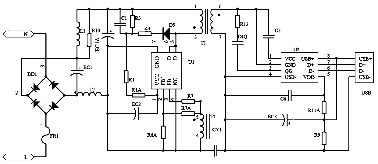
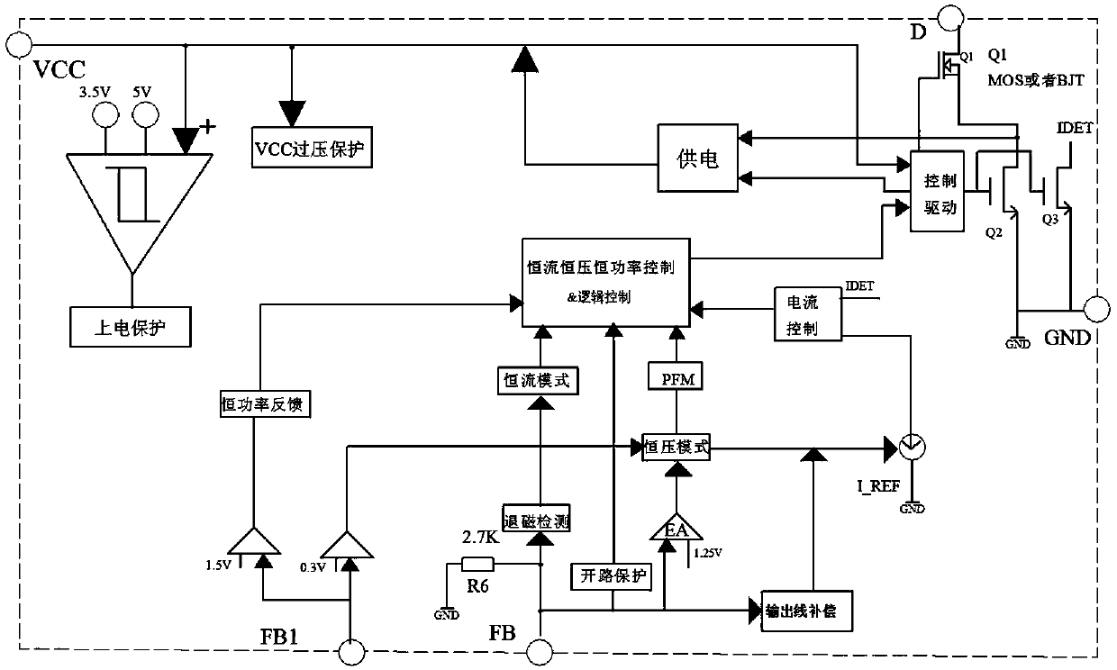
The invention belongs to the technical field of electronic device detection and the field of switching power supplies and relates to a novel loop detection and control circuit. The circuit includes aprimary circuit as an input end and a secondary circuit as an output end. A primary winding of the primary circuit is connected to a main control chip U1 which is in voltage division connection with an auxiliary winding of a transformer T1, and the auxiliary winding is connected with a voltage division resistor to supply power to an FB1 pin of the main control chip U1 such that the FB1 pin switches the working mode of the novel loop detection and control circuit. A secondary circuit of the secondary circuit is connected with a main control chip U2, a QG pin of the main control chip U2 is in RCdamping connection or short-circuit and half-short-circuit connection with the secondary winding. A first voltage threshold value of the FB1 pin is preset in the main control chip U1 to switch the working mode of the circuit, and a second voltage threshold value is preset in the main control chip U1 to judge the output voltage of the secondary circuit. According to the novel loop detection and control circuit, the multi-loop detection and self-powered functions can be realized, so the space is saved, and the cost is reduced.

Description

technical field [0001] The invention belongs to the technical field of electronic device detection and relates to a novel loop detection and control circuit. Background technique [0002] At present, the main switching power supplies on the market, especially low-power power supplies within 100W, no matter DC to DC or AC to DC, the main control circuit can usually only be made into constant current mode (commonly used in LED circuits), constant voltage plus constant current Mode (both PSR architecture and SSR architecture can be realized), constant voltage mode (conventional SSR architecture can be realized), or constant power mode (SSR architecture can be realized). However, since the feedback usually only has one output voltage feedback loop, it is impossible to realize the constant current mode in accordance with the requirements under certain conditions, and switch to the constant power mode under another condition. To realize this function, only constant power or consta...

Claims


Application Information

Patent Timeline
IPC IPC(8): H02M3/335
CPCH02M3/33507H02M3/33523
Inventor 严宗周
Owner SHENZHEN YUANNENG ELECTRIC CO LTD
Learn More