Notebook computer and its antenna structure

A technology of antenna structure and grounding wire, applied in the direction of antenna, radiating element structure, antenna support/installation device, etc., can solve problems such as the difficulty of electronic components, and achieve the effect of reducing the difficulty of space configuration and small antenna volume

Active Publication Date: 2011-05-25
WISTRON NEWEB
View PDF0 Cites 0 Cited by
  • Summary
  • Abstract
  • Description
  • Claims
  • Application Information

AI Technical Summary

Problems solved by technology

When planning the spatial configuration in the upper cover 3, the spacing between the antenna structure 6 and the antenna structure 7 needs to be considered in particular, which will cause difficulties in the spatial configuration of other electronic components (not shown) in the upper cover 3

Method used


Image

  • Notebook computer and its antenna structure
  • Notebook computer and its antenna structure
  • Notebook computer and its antenna structure

Examples


no. 1 example

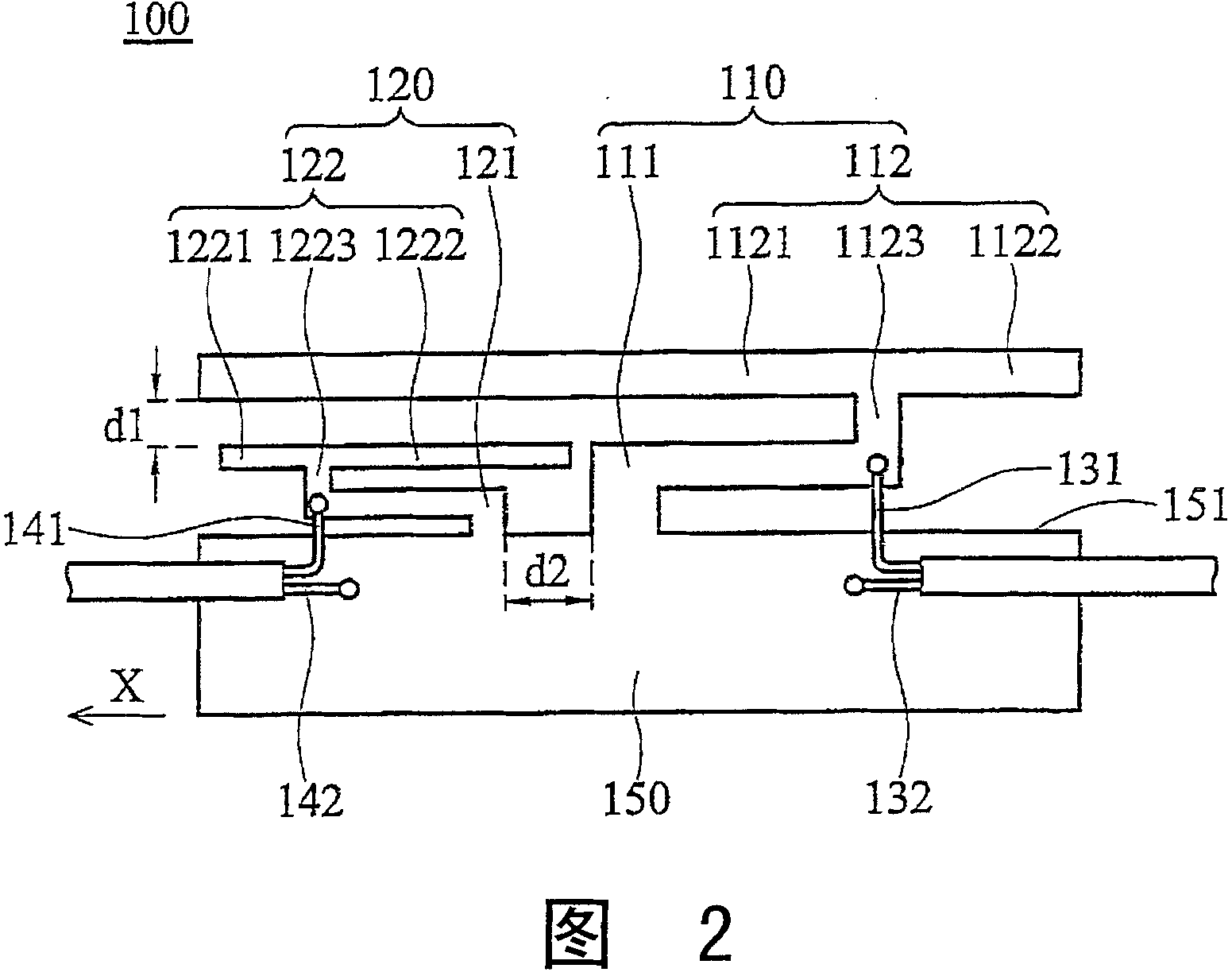
[0022] refer to figure 2 , which shows the antenna structure 100 of the first embodiment of the present invention, including a ground element 150, a first transceiver element 110, a second transceiver element 120, a first signal line 131, a first ground line 132, a second The signal line 141 and the second ground line 142 . Both the first transceiver element 110 and the second transceiver element 120 are connected to the ground element 150 . The first signal line 131 is coupled to the first transceiver element 110 , and the first ground line 132 is coupled to the ground element 150 . The second signal line 141 is coupled to the second transceiver element 120 , and the second ground line 142 is coupled to the ground element 150 . The first transceiver component 110 can send and receive a first wireless signal (900MHz) and a third wireless signal (1800MHz). The second transceiver component 120 can transmit and receive a second wireless signal (5GHz) and a fourth wireless sig...

no. 2 example

[0033] refer to Figure 5, which shows the antenna structure 100' of the second embodiment of the present invention. The difference between the second embodiment and the first embodiment is that the second transceiver element 120' (including the second L-shaped element 121' and the second radiation part 122') shape. Wherein, the free end of the second L-shaped element 121' extends toward the second direction, the second conductor 1223' connects the second L-shaped element 121', and the length of the third section 1221' is greater than that of the fourth section. 1222' length. In the second embodiment, the fourth wireless signal (26 Hz) is sent and received through the third section 1221', and the second wireless signal (5 GHz) is sent and received through the fourth section 1222'.

no. 3 example

[0035] refer to Figure 6a , which shows the antenna structure 200 of the third embodiment of the present invention, the difference between the third embodiment and the first embodiment lies in the first transceiving element 210 (including the first L-shaped element 211 and the first radiating part 212 ) shape. Wherein, the first conductor 2123 is connected to the first L-shaped element 211, the second section 2122 is connected to the first conductor 2123 and extends toward the second direction, the first section 2121 is connected to the second section 2122 and extending toward the first direction. The second section 2122 is an inverted U-shaped structure, including a first plate 261 , a second plate 262 and a third plate 263 , the first plate 261 is connected to the first conductor 2123 And the second plate 262 , the second plate 262 is connected to the third plate 263 . In the third embodiment, the first wireless signal (900 MHz) is sent and received through the first sec...


PUM


Abstract

The structure of antenna includes a grounding component, a first send receive component, and a second send receive component. The first send receive component includes a first L shaped component, and a first radiation sect. The first L shaped component is connected to the grounding component. The first radiation sect is connected to the first L shaped component. The first send receive component is in use for sending and receiving the first radio signal. The second send receive component includes a second L shaped component, and a second radiation sect. The second L shaped component is connected to the grounding component. The second radiation sect is connected to the second L shaped component. The second send receive component is in use for sending and receiving the second radio signal. Position of the second radiation sect is between the first radiation sect and the grounding component approximately.

Description

technical field [0001] The present invention relates to an antenna structure, in particular to an antenna structure capable of sending and receiving multiple wireless signals. Background technique [0002] refer to figure 1 , which shows a situation where the existing antenna structure is applied to a notebook computer (electronic device). The notebook computer 1 includes a main body 2 , a top cover 3 , a control interface 4 and a screen 5 . The control interface 4 is arranged on the body 2 . The screen 5 is disposed on the upper cover 3 . The antenna structure 6 is coupled to the cable 8 , and the antenna structure 7 is coupled to the cable 9 . Both the antenna structure 6 and the antenna structure 7 are disposed in the upper cover 3 . The antenna structure 6 is used to send and receive WWAN signals (including wireless signals with frequencies of 900MHz and 1800MHz), and the antenna structure 7 is used to send and receive WLAN signals (including wireless signals with fr...

Claims


Application Information

Patent Timeline
Patent Type & Authority Patents(China)
IPC IPC(8): H01Q1/22H01Q1/38H01Q21/28H01Q13/08
Inventor 刘志凯郑维礼
Owner WISTRON NEWEB
Why Eureka
Try Eureka