Microstrip monopole antenna

A technology of monopole antenna and microstrip, which is applied in the direction of antenna grounding device, antenna grounding switch structure connection, radiation element structure, etc. It can solve the problems such as difficult to control antenna beam pointing, short service life of antenna, easy to be worn out, etc. Achieve the effect of reducing design difficulty and production cost, prolonging service life and increasing bandwidth

Active Publication Date: 2020-05-22
NANJING UNIV OF SCI & TECH
View PDF11 Cites 0 Cited by
  • Summary
  • Abstract
  • Description
  • Claims
  • Application Information

AI Technical Summary

Problems solved by technology

[0005] Most of the existing microstrip monopole antennas work in the middle and low frequency bands, with limited bandwidth, and it is difficult to control the antenna beam pointing
In addition, the main radiation oscillator of the existing microstrip monopole antenna is exposed in the air, which is easy to be worn, rusted, etc., and the service life of the antenna is relatively short

Method used


Image

  • Microstrip monopole antenna
  • Microstrip monopole antenna
  • Microstrip monopole antenna

Examples


Embodiment

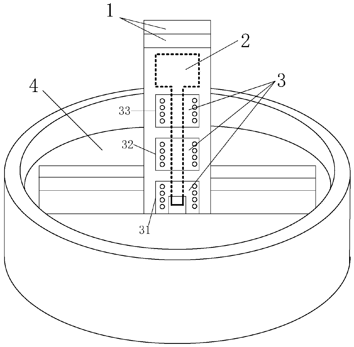
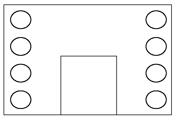
[0025] Such as figure 1 , 2 As shown, the microstrip monopole antenna of the present invention includes a double-layer dielectric substrate 1, a main radiation element 2 attached to the middle layer of the two-layer dielectric substrate 1, and a guide patch layer 3 attached to the front and rear surfaces of the dielectric substrate 1, And the metal ground layer 4, the antenna patch layer 3 includes a bottom guide patch 31, a middle guide patch 32, and a top guide patch 33, and a gap is provided between each adjacent patch, and the gap is not greater than The thickness of the dielectric substrate 1; the installation position of the guide patch on the back is corresponding to the guide patch on the front; the main radiation element 2 is directly connected to the feeding network.

[0026] The energy of the main radiating oscillator 2 is concentrated in the side-radiation direction, so the energy obtained by the directing patch through coupling is less. In order to enhance the co...


PUM

PropertyMeasurementUnit
Thicknessaaaaaaaaaa

Abstract

The invention discloses a microstrip monopole antenna. The antenna comprises two layers of dielectric substrates, a main radiation oscillator attached to an interlayer between the two layers of dielectric substrates, guide patch layers attached to the front and rear surfaces of the dielectric substrates, and a metal grounding layer, antenna patch layers comprise a bottom guide patch, a middle guide patch and a top guide patch, and a gap is formed between every two adjacent patches; the arrangement positions of the guide patches on the back surface correspond to those of the guide patches on the front surface; and the main radiation oscillators are directly connected with the feed network. According to the microstrip monopole antenna, forward radiation is realized, the antenna wave beam isfunnel-shaped, the microstrip monopole antenna can be used as a missile-borne antenna, and the antenna bandwidth is wide enough.

Description

technical field [0001] The invention belongs to the technical field of microwave antennas, in particular to a microstrip monopole antenna with sufficiently wide bandwidth that can meet the beam pointing requirements of missile-borne antennas. Background technique [0002] In the ground-to-ground missile missile antenna, because it has a funnel-shaped beam requirement for the antenna beam, the missile antenna often needs to be conformal on the missile body, which makes its design complicated. [0003] The microstrip antenna is on a thin dielectric substrate, one side is attached with a thin metal layer as a ground plane, and the other side is made of a metal patch of a certain shape by photolithography and other methods, and the patch is connected by a microstrip line or a coaxial probe The feed constitutes the antenna. If the shape of the patch is a slender strip, it is a microstrip dipole antenna. When the patch is an area unit, it is a microstrip antenna. The microstrip ...

Claims


Application Information

Patent Timeline
IPC IPC(8): H01Q1/38H01Q1/48H01Q1/50
CPCH01Q1/38H01Q1/48H01Q1/50
Inventor 张淑宁徐焕昊蒋旭峰
Owner NANJING UNIV OF SCI & TECH
Why Eureka
Try Eureka