Door with a rotatably mounted door leaf

A technology of rotating support and door leaf, which is applied to the suspension device of wing leaf, switches with brakes, windows/doors, etc., which can solve the problems of incomplete structure and other problems.

Inactive Publication Date: 2007-02-21
DORMA GMBH & CO KG
View PDF0 Cites 0 Cited by
  • Summary
  • Abstract
  • Description
  • Claims
  • Application Information

AI Technical Summary

Problems solved by technology

[0002] Such doors, although sufficiently known, are still not fully

Method used


Image

  • Door with a rotatably mounted door leaf
  • Door with a rotatably mounted door leaf
  • Door with a rotatably mounted door leaf

Examples


Embodiment Construction

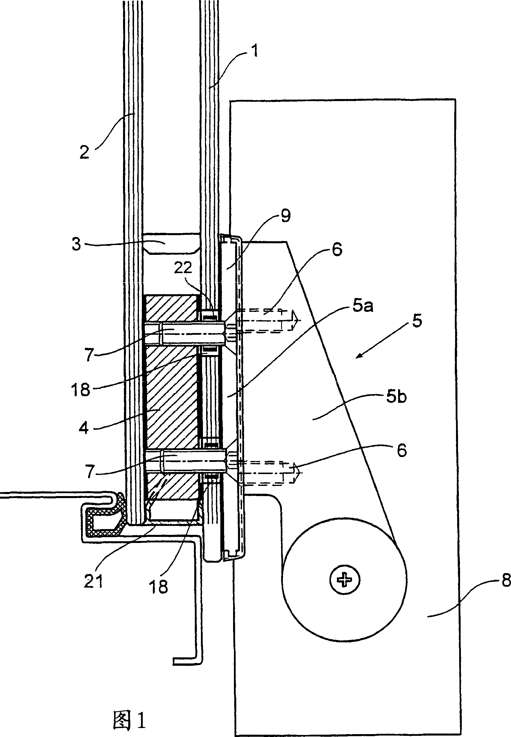
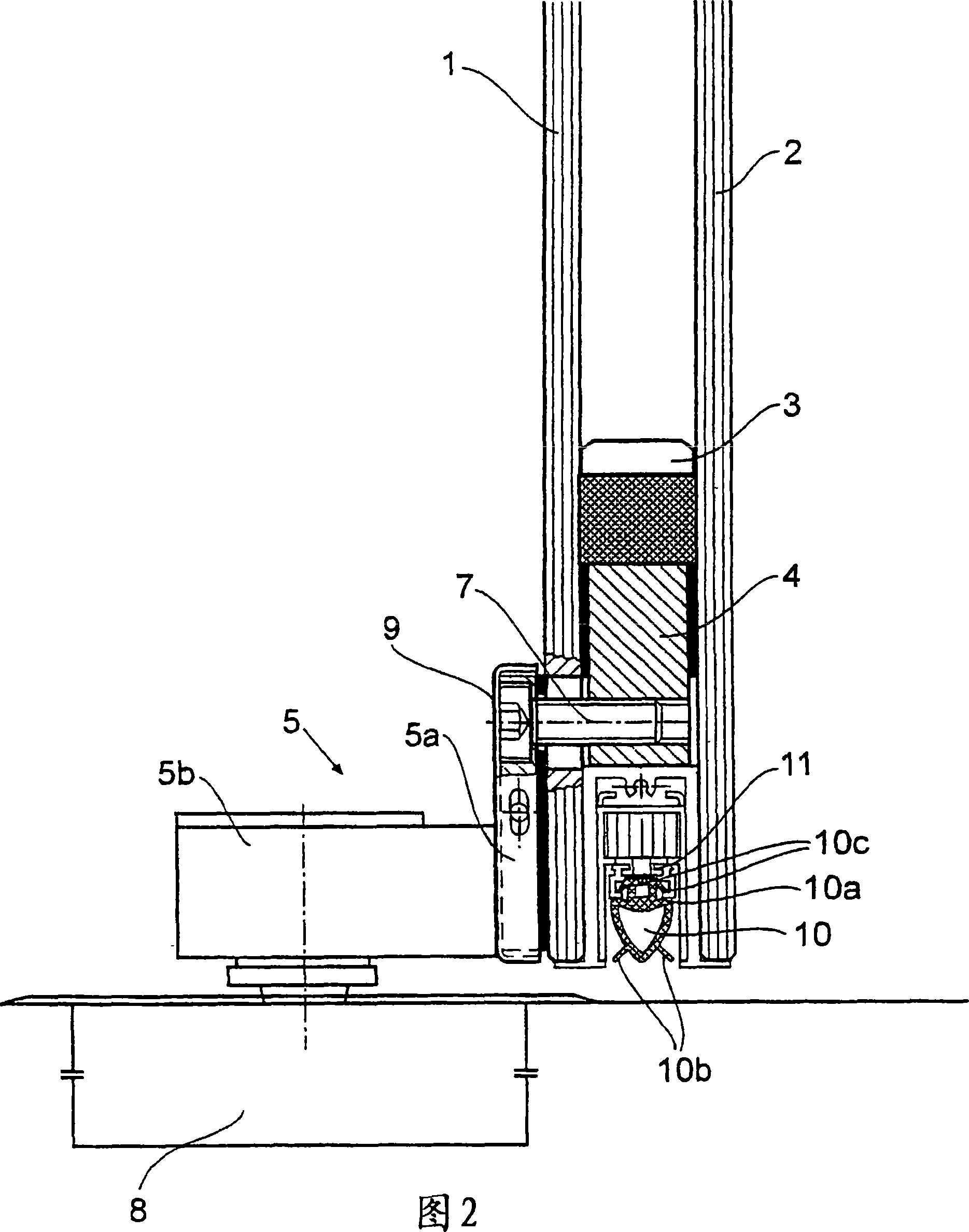
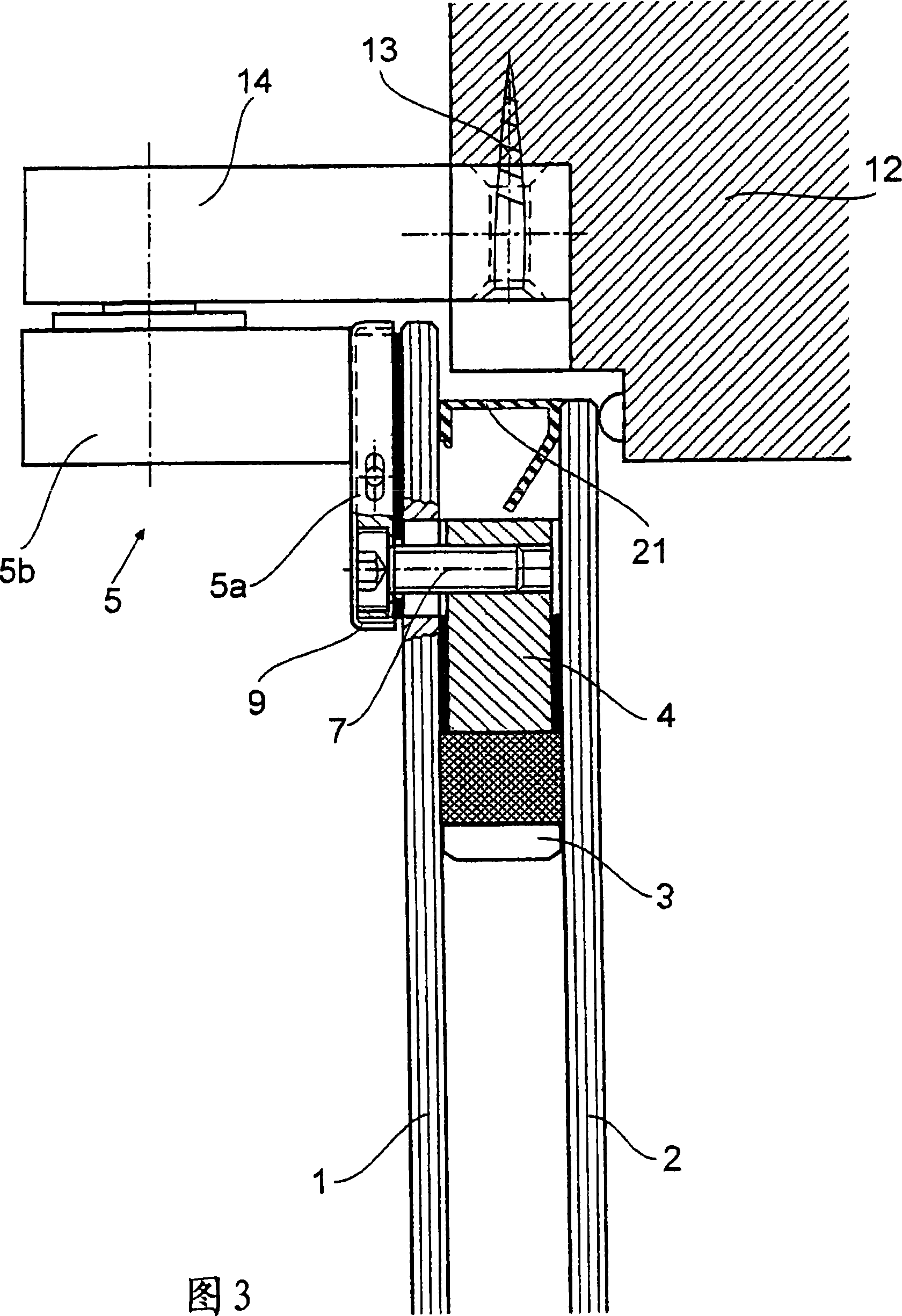
[0023] The door basically comprises two glass panes 1 , 2 arranged parallel to one another, between which a spacer 3 is inserted. A carrier element 4 is inserted between the two glass panes 1 , 2 in the region of the pivot bearing of the door. The support element 4 is connected to a corresponding support 5, which is designed as an angle profile and has a vertical side 5a and a horizontal side 5b. The vertical side 5a is screwed to the horizontal side 5b by means of screws 6, from which the screws are screwed into the horizontal side 5b, so that in the assembled state the screw heads point, for example, towards the glass pane 1 (see FIG. 1 ) and are therefore invisible from the outside.

[0024] The vertical sides 5 a rest on the outside of the glass pane 1 and are screwed to the support element 4 arranged between the two glass panes 1 , 2 by means of screws 7 , wherein the screws 7 lead into the glass pane 1 through holes 18 middle. The thread of the screw 7 is provided wit...


PUM


Abstract

The invention relates to a door with a rotatably mounted door leaf, which may be operated by a floor door closer, arranged below the door, whereby the door leaf is embodied with at least two parallel glass panes, a peripheral spacer between the glass panes and a support element arranged between the glass panes in the lower region of the door leaf. According to the invention, such a door may be improved, in particular with regard to the pivot mounting thereof, whereby the support element between the glass panes may be connected to a support, lying on the outside of the glass panes, which may engage with a drive axle of the floor door closer, outside the plane of the door.

Description

technical field [0001] The invention relates to a door with a rotatably mounted door leaf, which can be driven by a floor spring (Bodentürschlie Ber) arranged below the door, wherein the door leaf consists of at least two glass panes arranged in parallel, one between the glass panes The surrounding spacer and a support element arranged between the glass panes in the door leaf. Background technique [0002] Although such doors are sufficiently known, their construction in the area of ​​the swivel bearing is still not fully developed. Contents of the invention [0003] It is therefore the object of the invention to improve a door of the type mentioned at the outset, in particular with regard to its swivel bearing and operating comfort. [0004] This object is achieved in a door with a rotatable door leaf which can be driven by a floor spring arranged below the door in the floor, wherein the door leaf consists of at least two glass panes arranged in parallel, one on each gla...

Claims


Application Information

Patent Timeline
IPC IPC(8): E06B3/02E05D15/00E05F3/22E05D5/02
CPCE05Y2800/672E05F3/225E05Y2800/27E05D5/0246E05Y2900/132E06B3/025E05Y2800/12E05Y2800/205E05Y2800/21E05Y2900/00
Inventor H·赫特
Owner DORMA GMBH & CO KG
Why Eureka
Try Eureka