Thin ic tag and method of producing the same

A manufacturing method and label technology, which are applied in the directions of antenna, printing, antenna support/installation device, etc., can solve the problems of limited miniaturization and limited range of thin IC tags 10, etc.

Inactive Publication Date: 2007-02-21
ORMON CORP
View PDF3 Cites 6 Cited by
  • Summary
  • Abstract
  • Description
  • Claims
  • Application Information

AI Technical Summary

Problems solved by technology

[0015] However, when the capacitance C in the IC chip 11 is preset, in order to obtain the above-mentioned frequency of 13.56 MHz for non-contact communication, the outer dimension R1, the inner dimension R2, and the number of turns T of the antenna coil 12 can be simply changed. The range is limited, so the miniaturization of the thin IC tag 10 is also limited

Method used


Image

  • Thin ic tag and method of producing the same
  • Thin ic tag and method of producing the same
  • Thin ic tag and method of producing the same

Examples


no. 2 approach

[0067] The following is based on Figure 5 Another embodiment of the thin IC tag and its manufacturing method of the present invention will be described. In addition, for convenience of description, components having the same functions as those described in the first embodiment are denoted by the same reference numerals, and description thereof will be omitted. In this embodiment, differences from the first embodiment described above will be described.

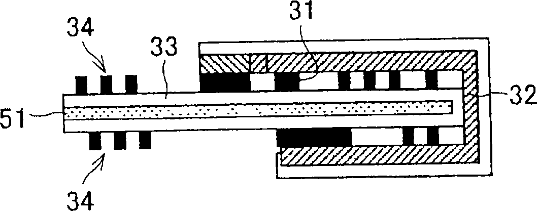
[0068] The thin IC tag described in the first embodiment is configured such that an adhesive layer 51 is formed on the surface of the electronic component holding film 30 opposite to the surface on which the electronic component module 32 and the like are mounted, and the bending direction is As opposed to the surface side on which the adhesive layer 51 is formed, the thin IC tag of this embodiment is configured such that an adhesive layer is formed on the surface of the electronic component holding film 30 on which the elect...


PUM


Abstract

An electronic part holding film (30) includes an electronic part module (32) and winding conductor patterns (34a, 34b). The winding conductor patterns (34a, 34b) have ends in which terminal pads (35, 36) are formed and to which a connecting part (37) is not connected, respectively. The terminal pads (35, 36) are electrically connected to each other via the electronic part module (32). The electronic part holding film (30) is folded at a folding position (38). In this way, a thin IC tag (20) is manufactured. According to the thin IC tag (20), it is possible to provide a thin IC tag which does not increase the number of manufacturing steps and the manufacturing cost and on which an electronic part and the like can be mounted with ease.

Description

technical field [0001] The present invention relates to a flexible and thin IC tag suitable for use as an IC tag with a built-in receipt that can be read without contact using an induced electromagnetic field, and more particularly to a thin IC tag for making a small IC tag. Labels and methods of making them. Background technique [0002] In order to promote the automation of logistics, it is important to allow mechanical reading of the contents of receipts and the like attached to individual items. Conventionally, for this purpose, a barcode label corresponding to the content is affixed to each receipt. [0003] However, in order to read a barcode label by a so-called barcode reader, it is necessary to establish a relationship between a certain distance and a direction between the two with high precision, which hinders smooth logistics. In addition, the amount of information that can be input into the barcode is small, and the scope of logistics management is also limited...

Claims


Application Information

Patent Timeline
Patent Type & Authority Applications(China)
IPC IPC(8): G06K19/077B42D15/10G06K19/07H01Q7/02H01Q1/22H01Q7/00
CPCG06K19/07718H01Q7/00H01Q1/22G06K19/07783G06K19/07749G06K19/07779G06K19/07784G06K19/07G06K19/077H01Q7/02
Inventor 川井若浩
Owner ORMON CORP
Why Eureka
Try Eureka