Adaptive energy-saving wall

An adaptable and wall technology, applied in the field of adaptable energy-saving walls, can solve the problems of increasing building energy consumption and hindering the dissipation of waste heat in buildings, achieving strong adaptability and operability, light weight, and saving man-hours. Effect

Inactive Publication Date: 2007-02-28
SHANGHAI JIAO TONG UNIV
View PDF1 Cites 15 Cited by
  • Summary
  • Abstract
  • Description
  • Claims
  • Application Information

AI Technical Summary

Benefits of technology

This new type of material called an adiabatic wall helps save more than 50% of electricity compared with traditional walls made from materials like concrete or steel. Its advantages include being easy to install at home without much labor cost, reducing environmental impact by making it lighter while still maintaining good thermal properties, allowing better control over temperature, and enhancing sunlight absorption efficiency during daytime hours.

Problems solved by technology

This patented technical solution describes how saving energy can be achieved by creating better ways to prevent overexposure on buildings while still maintain their effectiveness.

Method used


Image

  • Adaptive energy-saving wall
  • Adaptive energy-saving wall

Examples


Embodiment Construction

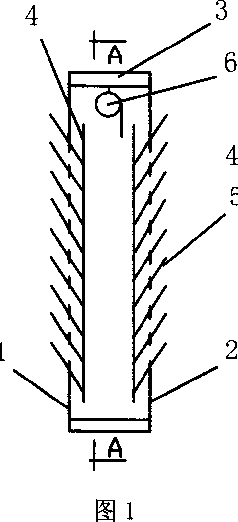
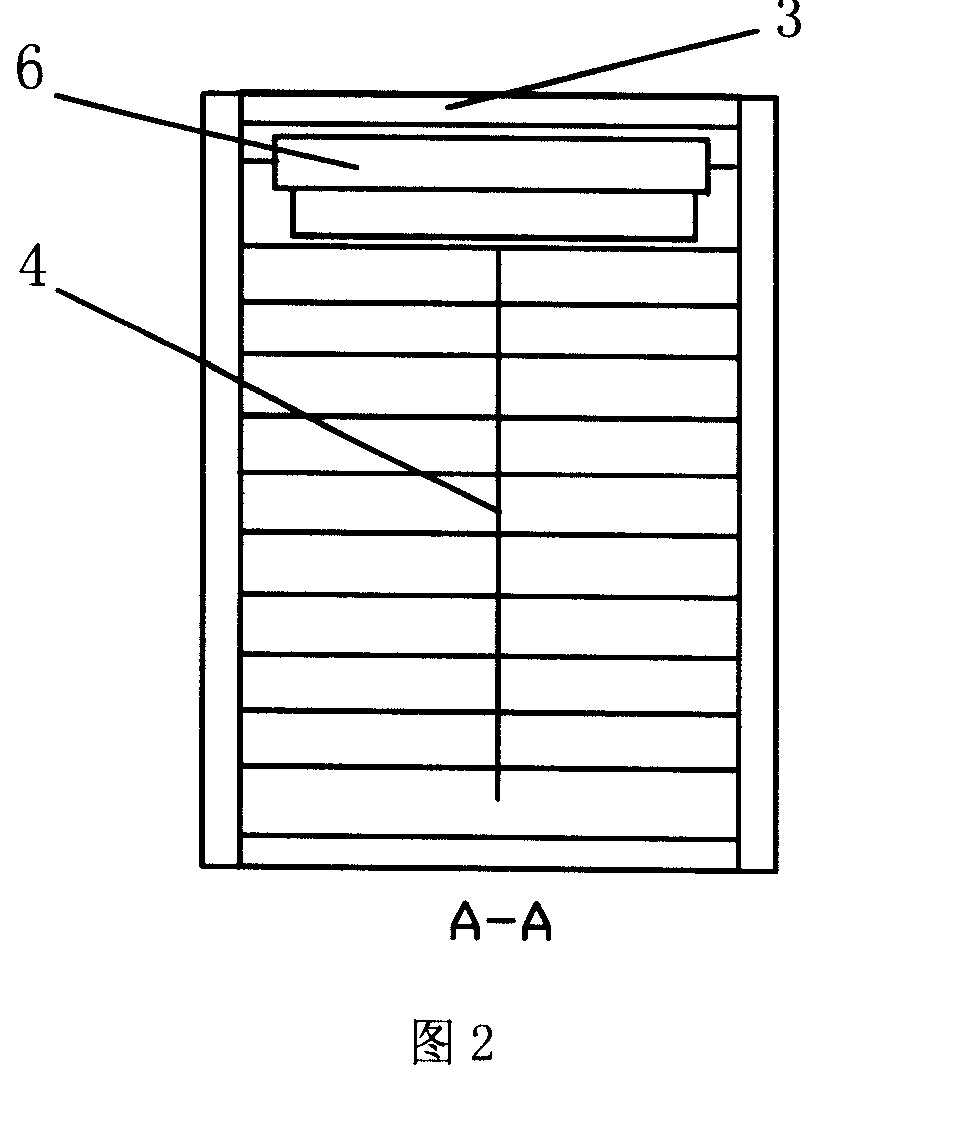
[0013] As shown in FIGS. 1-2 , the present invention includes an inner wall panel 1 , an outer wall panel 2 , a heat insulation frame 3 , a moving link 4 , movable louvers 5 , and a heat insulation roller blind 6 .

[0014] The inner wall panel 1 and the outer wall panel 2 are closely connected with the two end faces of the heat insulation frame 3 respectively, and both the inner wall panel 1 and the outer wall panel 2 are equipped with a number of movable louvers 5, which are connected with the moving connecting rod 4 for heat insulation. The roller blind 6 is fixed on the inner upper frame of the heat insulation frame 3 . Both the inner wall panel 1 and the outer wall panel 2 are made of stainless steel metal material, the heat insulation frame 3 is made of polyurethane hard foam imitation wood material, and the heat insulation roller shutter 6 is made of coiled aluminum foil with good heat insulation performance. One surface of the louver 5 is coated with an aluminum alloy ...


PUM


Abstract

The invention relates to an adaptive energy-saving wall, wherein said invention comprises: an inner wall plate, an outer wall plate, a thermal-insulated frame, a movable connecting rod, a movable blind, and a thermal-insulated blind; said inner and outer wall plates are connected to two end surfaces of thermal-insulated frame; the inner and outer wall plates are both mounted with several movable blinds connected to the movable connecting rod; the thermal-insulated blind is fixed at the inner upper frame of thermal-insulated frame; one surface of movable blind is plated with aluminum alloy film with high reflective index, while another surface is coated with black layer with high adsorption index. The invention has lower weight, thermal-insulated ability and energy-saving property.

Description


Claims


Application Information

Patent Timeline
Owner SHANGHAI JIAO TONG UNIV
Why Eureka
Try Eureka