Hydraulic active damping system for gears and method

An active damping, hydraulic technology, applied in the direction of gear vibration/noise attenuation, belt/chain/gear, transmission parts, etc., can solve the problems of reduced mechanical efficiency of the system and increased resistance of the gear shaft where the gear is installed, so as to increase efficiency, Reducing the effect of tooth knocking

Inactive Publication Date: 2007-02-28
GM GLOBAL TECH OPERATIONS LLC
View PDF0 Cites 5 Cited by
  • Summary
  • Abstract
  • Description
  • Claims
  • Application Information

AI Technical Summary

Problems solved by technology

Fulfillment of each of these hopes results in increased drag on the gear shaft on which the gear is mounted, and this drag is constant
This inherent resistance makes the system less mechanically efficient

Method used


Image

  • Hydraulic active damping system for gears and method
  • Hydraulic active damping system for gears and method
  • Hydraulic active damping system for gears and method

Examples


Embodiment Construction

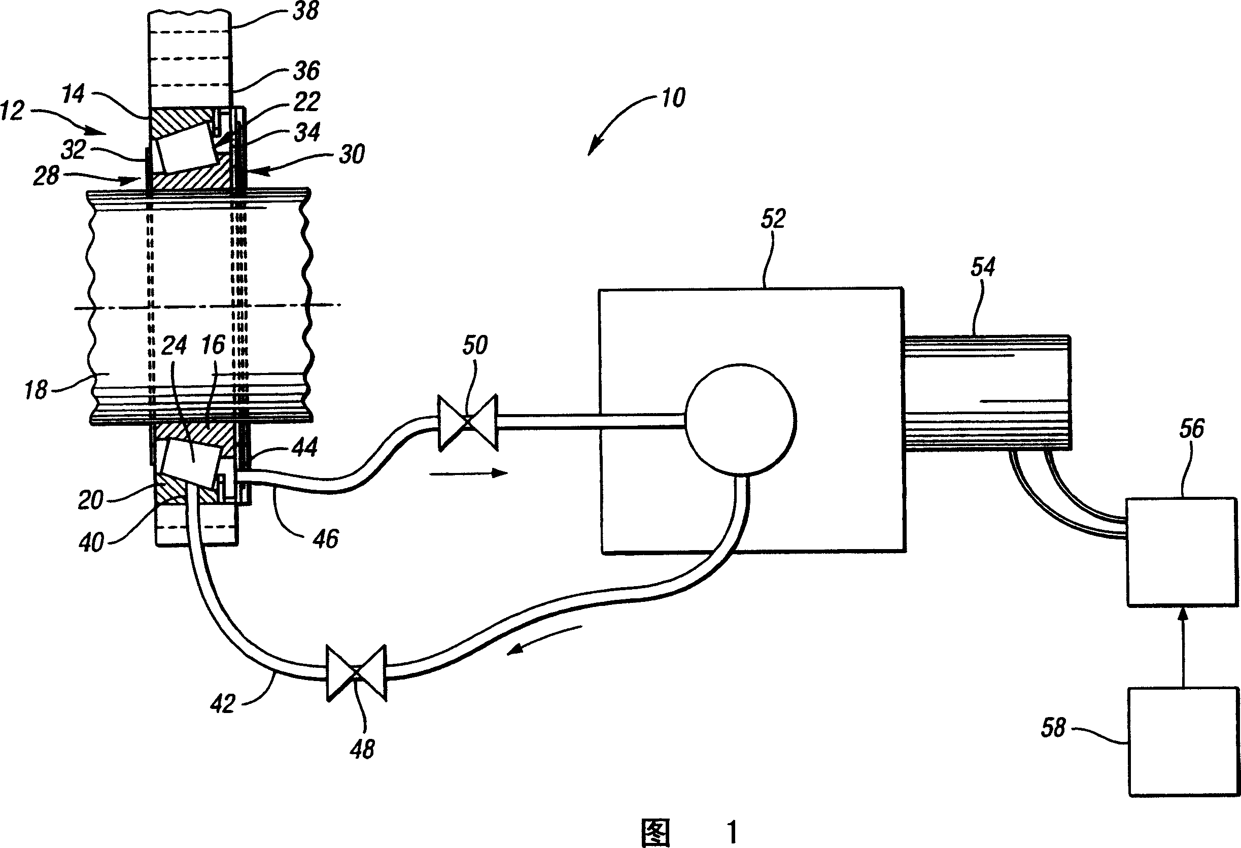
[0015] FIG. 1 is a schematic diagram of a hydraulic active damping system 10 of the present invention. The hydraulic unit 12 is a sealed or enclosed dedicated roller bearing 14 having an inner ring 16 axially disposed relative to a shaft 18 . Around the inner ring 16 is an outer ring 20 . The inner ring 16 and the outer ring 20 together define a void or enclosure 22 in which a plurality of roller elements 24 are disposed. The first axial side 28 and the second axial side 30 of the dedicated roller bearing 14 are sealed by a first seal 32 and a second seal 34 . Mounted with the outer ring 20 is a gear 36 which is in meshing contact with a gear 38 .

[0016] The hydraulic unit 12 also includes a fluid supply port 40 operable to form a passage through which pressurized fluid may flow from the fluid supply mechanism 42 into the void or enclosure 22 not occupied by the plurality of roller elements 24 . The location of the fluid supply port 40 may be dictated by component design...


PUM


Abstract

The present invention provides a hydraulic active damping system to damp gears, thereby reducing the occurrence of gear rattle or noise. The active nature of the present invention will allow the drag within the bearing to which the gear mounts to be selectively increased, by pressurizing an enclosed or specialized bearing with fluid during critical events. The pressure within the specialized bearing is subsequently decreased, thereby only increasing the system drag at critical operating conditions. The present invention also provides a method of damping gears by introducing pressurized fluid into a specialized bearing and subsequently reducing the fluid pressure therein.

Description

technical field [0001] The invention relates to a driving gear damping mechanism. Background technique [0002] During brief relative speed changes between the driving and driven gears, the intermeshing gears sometimes produce noise and chatter. This can occur, for example, in manual shift or countershaft transmissions. A countershaft transmission includes an input shaft, a countershaft and an output shaft. The input shaft and intermediate shaft are connected to each other through gears (head gear set) meshing. The countershaft and output shaft are interconnected by sets of meshing gears (change gears) which are selectively connected to one of the shafts by a synchronizer clutch arrangement. Therefore, there are multiple sets of gear meshes between the input and output shafts. The speed ratio between the input shaft and the output shaft is controlled by the meshed transmission gear. The speed ratio between the input and output shafts is varied by means of interchanging ...

Claims


Application Information

Patent Timeline
Patent Type & Authority Applications(China)
IPC IPC(8): F16H57/00
CPCF16H57/0469F16C19/364F16F15/161F16H57/0434F16H57/043F16H57/0427F16H57/0006F16C25/08Y10T74/19907Y10T74/19623
Inventor M·F·奥利里D·A·吉尔伯特J·S·雷斯
Owner GM GLOBAL TECH OPERATIONS LLC
Why Eureka
Try Eureka