Detector with same flatness

A detection equipment, coplanar technology, applied in the direction of measurement devices, mechanical measurement devices, instruments, etc., can solve the problems of poor detection accuracy and time-consuming inspection personnel, and achieve the effect of high detection accuracy

Inactive Publication Date: 2007-02-28
SPEED TECH
View PDF0 Cites 2 Cited by
  • Summary
  • Abstract
  • Description
  • Claims
  • Application Information

AI Technical Summary

Problems solved by technology

However, using a manual method to detect the electromagnetic wave shielding shell 110 not only requires a large number of detection personnel to spend a lot of time, but also has poor detection accuracy.

Method used


Image

  • Detector with same flatness
  • Detector with same flatness

Examples


Embodiment Construction

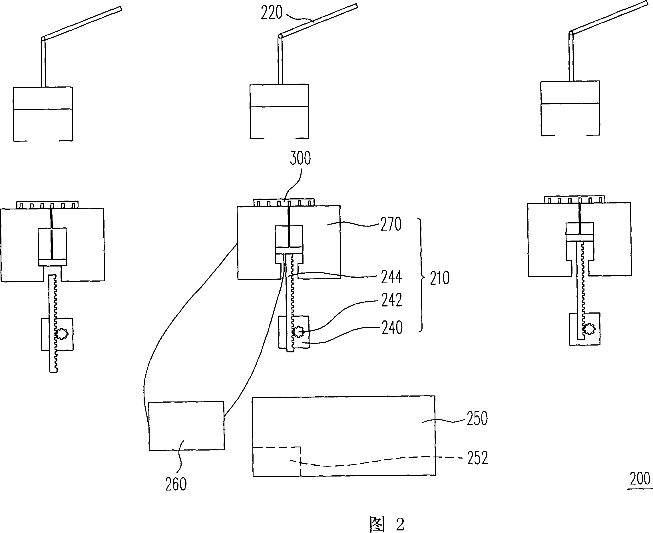
[0022] Fig. 2 is a partial schematic diagram of a coplanarity testing device according to an embodiment of the present invention. Please refer to FIG. 2 , the coplanarity detection device 200 is used to detect the coplanarity of multiple test points on the test object 300 . The object under test 300 is, for example, an electromagnetic wave shielding case for electronic products, or other various items that need to be tested for coplanarity. The coplanarity testing device 200 includes a testing module 210 , a transport device 220 and a servo controller 250 . Wherein, each detection module 210 includes a detection rod 230 , a motor 240 and a platform 270 . The platform 270 is used to place the object under test 300 for detection, and the platform 270 has a through hole 272 . The detection rod 230 is disposed under the platform 270, and the detection rod 230 is suitable for actuating in the through hole 272 to detect the point to be measured. In addition, the probing rod 230 i...


PUM


Abstract

The invention relates to a coplanar tester, which can test the coplanar degree of several testing point of several objects. Said tester comprises: several testing modules, several carriers and one servo controller; one testing module comprises platform, detecting rod, and motor; the platform is used to lay tested object; the detecting rod is under the platform; the motor drives the detecting rod; the carrier is beside the platform, to move the object to the platform; the servo controller is connected to the motor, to control the carrier to move the object to the platform, and control the motor to drive the detecting rod upwards, to obtain the height information of tested point, and judge their coplanar degree.

Description

【Technical field】 [0001] The present invention relates to a detection device, and in particular to a coplanarity detection device. 【Background technique】 [0002] With the advancement and development of science and technology, although various electronic product 3C integration systems and equipment bring infinite convenience to human life, they also create a complex electromagnetic wave error environment, which is the so-called Electro-Magnetic Interference (Electro-Magnetic Interference, EMI), also known as electronic noise. [0003] Electromagnetic wave is the general term for electric wave and magnetic wave. To put it simply, the current flowing in the wire will generate a magnetic field with the same frequency around the wire, so there will be fluctuations in both the electric field and the magnetic field around the wire, which is the so-called electromagnetic wave. In many medical literatures, it is pointed out that no matter the source of electromagnetic waves is fro...

Claims


Application Information

Patent Timeline
Patent Type & Authority Applications(China)
IPC IPC(8): G01B5/00
Inventor 游川贤程光宇刘定国
Owner SPEED TECH
Why Eureka
Try Eureka