
Pneumatic pipe joint testing device and detection method thereof

A testing device and pneumatic tube technology, which can be applied to measuring devices, fluid tightness testing, and machine/structural component testing, etc., can solve the problems of high cost, single testing method, complicated replacement of pipe joints, etc., and achieve high accuracy , the effect of high efficiency

Pending Publication Date: 2019-03-15
宁波奉化亿太诺流体管件有限公司
View PDF0 Cites 0 Cited by
  • Summary
  • Abstract
  • Description
  • Claims
  • Application Information

AI Technical Summary

Problems solved by technology

[0002] At present, the leak detection of pipe joints in the domestic processing industry adopts the linear intermittent leak detection method or the rotary continuous leak detection method. When using the linear intermittent leak detection method, it is necessary to wait for the pipe joints to be in place and the conveyor belt stops positioning before testing, resulting in The pipe joints that are continuously conveyed in the back need to be stopped, etc. If the detection will cause the pipe joints in the back to be blocked and missed inspections, and the output at the same station is low. When the rotating continuous leak detection method is used, the output of this machine is high, but the corresponding cost It is relatively high, occupies a large area, and the customer input cost is too high, and it is more complicated to replace the pipe joint
Therefore, when performing leak detection on pipe joints, neither the linear intermittent leak detection method nor the rotary continuous leak detection method can simultaneously achieve low-cost, online continuous leak detection and high-speed, high-yield production methods, and cannot meet the needs of the market.
In addition, this detection method is single, the detection efficiency is low, and it cannot play the role of alarm, which affects the recycling of substandard products

Method used


Image

  • Pneumatic pipe joint testing device and detection method thereof
  • Pneumatic pipe joint testing device and detection method thereof
  • Pneumatic pipe joint testing device and detection method thereof

Examples


Embodiment Construction

[0026] The specific implementation manners of the present invention will be further described below in conjunction with the accompanying drawings, so as to make the technical solution of the present invention easier to understand and grasp.

[0027] In this embodiment, it should be understood that the terms "middle", "upper", "lower", "top", "right side", "left end", "above", "back", "middle", etc. The indicated orientation or positional relationship is based on the orientation or positional relationship shown in the drawings, and is only for the convenience of describing the present invention, rather than indicating or implying that the referred device or element must have a specific orientation, be constructed and operated in a specific orientation , and therefore cannot be construed as a limitation of the present invention.

[0028] In addition, in this specific embodiment, if the connection or fixing method between the components is not specified in particular, the connect...


PUM


Abstract

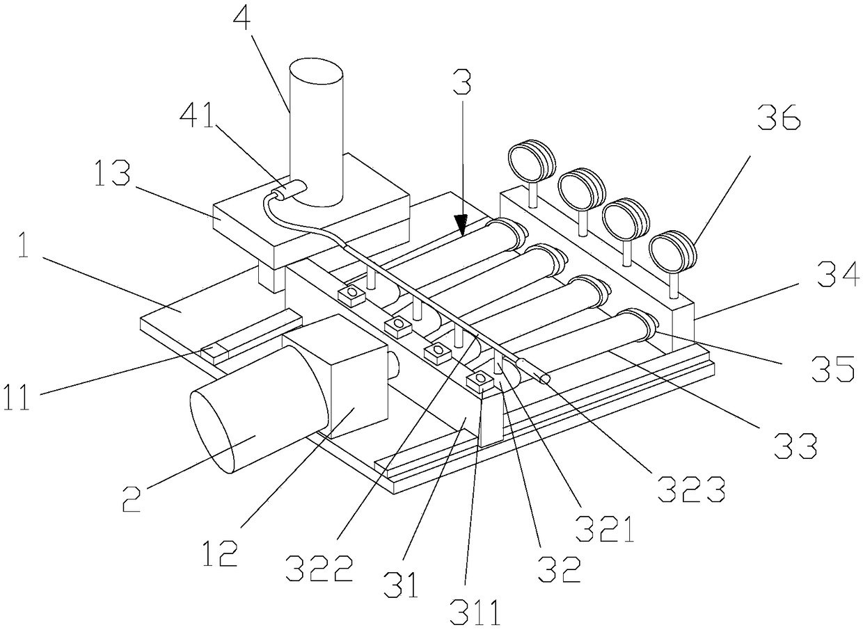
The invention discloses a pneumatic pipe joint testing device and a detection method thereof. The pneumatic pipe joint testing device comprises a detection platform, a driving cylinder, a detection device, a detection cylinder, a second sleeve joint seat and an air pressure meter; the detection device comprises a moving seat, a first sleeve joint seat, a pipe joint and a fixed seat, wherein one side of the moving seat is connected with the driving cylinder; the first sleeve joint seat is arranged on the moving seat, one end of the pipe joint hermetically sleeves the first sleeve joint seat, the fixed seat is arranged at the other end of the pipe joint, the second sleeve joint seat is arranged on the fixed seat corresponding to the pipe joint, and the air pressure meter is arranged on the fixed seat; the detection platform of the device is provided with the first sleeve joint seat and the second sleeve joint seat, so that a plurality of pipe joints can be detected simultaneously when the device is used; the pneumatic pipe joint testing device has the advantages of automatic detection, high accuracy and high efficiency.

Description

technical field [0001] The invention specifically relates to a pneumatic pipe joint testing device and a testing method thereof. Background technique [0002] At present, the leak detection of pipe joints in the domestic processing industry adopts the linear intermittent leak detection method or the rotary continuous leak detection method. When using the linear intermittent leak detection method, it is necessary to wait for the pipe joints to be in place and the conveyor belt stops positioning before testing, resulting in The pipe joints that are continuously conveyed in the back need to be stopped, etc. If the detection will cause the pipe joints in the back to be blocked and missed inspections, and the output at the same station is low. When the rotating continuous leak detection method is used, the output of this machine is high, but the corresponding cost It is relatively high, occupies a large area, and the customer's input cost is too high, and it is more complicated t...

Claims


Application Information

Patent Timeline
IPC IPC(8): G01M3/28
CPCG01M3/2853
Inventor 孙光锋孙驰凯
Owner 宁波奉化亿太诺流体管件有限公司
Learn More