
Antenna feeding device and mobile communication terminal with the same

A mobile communication terminal and feeding device technology, which is applied in the direction of antenna support/installation device, antenna, antenna parts, etc., can solve the problems of unstable contact pressure at the antenna connection part, unfavorable mass production operation, loss of electromotive force, etc., to achieve Effects of reducing electromotive force loss, stabilizing fixed force, and increasing contact area

Inactive Publication Date: 2007-02-28
LG ELECTRONICS (CHINA) R&D CENT CO LTD
View PDF0 Cites 1 Cited by
  • Summary
  • Abstract
  • Description
  • Claims
  • Application Information

AI Technical Summary

Problems solved by technology

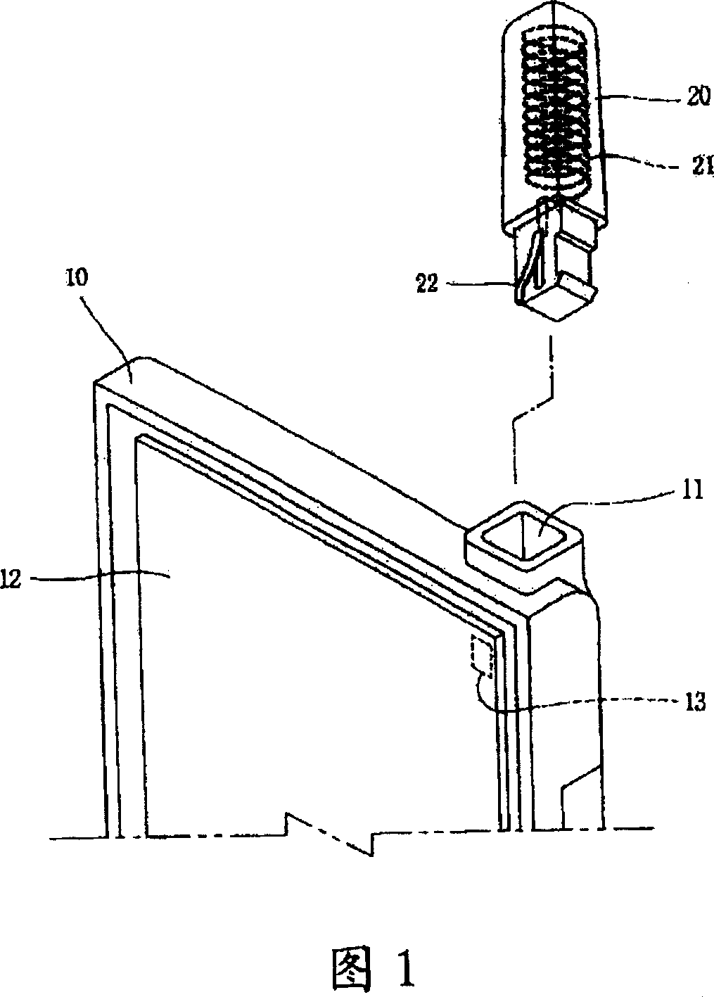
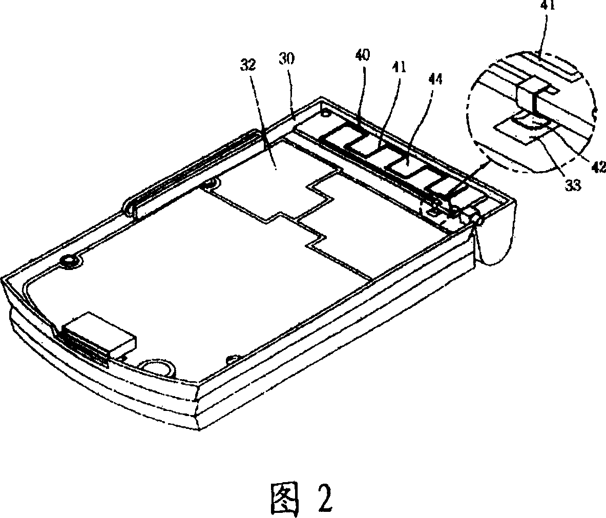
[0010] However, in the feeding device of the above-mentioned prior art antenna, because the elasticity of the above-mentioned feeder wires 22, 42 naturally becomes weaker with time and the use environment, this will make the contact pressure provided to the above-mentioned antenna connecting parts 13, 33 in an insignificant range. stable state
Moreover, the above-mentioned feeder lines 22, 42 are each formed into a curved shape for generating elastic force, so that the above-mentioned feeder lines 22, 42 themselves may lose electromotive force, and due to the contact area between the above-mentioned feeder lines 22, 42 and the antenna connection parts 13, 33 narrower, which will also cause a loss of EMF
[0011] Moreover, since the above-mentioned feeder lines 22, 42 form a three-dimensional space shape in an elongated state, the positions of the contact points on the above-mentioned antenna connecting parts 13, 33 may vary according to the assembled state, which is not conducive to homogeneous product quantity. production operation

Method used


Image

  • Antenna feeding device and mobile communication terminal with the same
  • Antenna feeding device and mobile communication terminal with the same
  • Antenna feeding device and mobile communication terminal with the same

Examples


Embodiment Construction

[0036] The object of the present invention is to provide an antenna feeding device and a mobile communication terminal provided with the antenna feeding device.

[0037] The antenna feeding device and the beneficial embodiments of the mobile communication terminal provided with the antenna feeding device in the present invention will be described in detail below with reference to the accompanying drawings, and the detailed description of related known functions or components will be omitted.

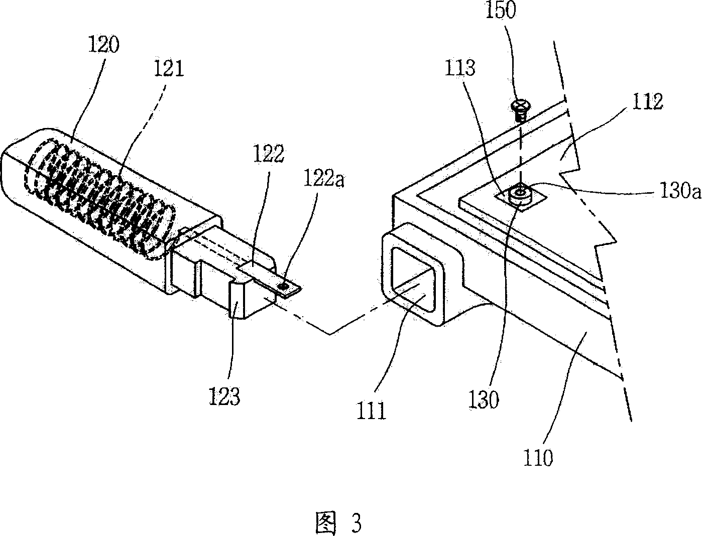
[0038] FIG. 3 is a perspective view of an antenna feeding device used in a mobile communication terminal with an external antenna as an embodiment of the present invention.

[0039] As shown in the figure, an antenna installation hole 111 for inserting and fixing the antenna 120 is formed on the upper side of the housing 110 of the mobile communication terminal, and a circuit board 112 is fixed inside the housing 110 .

[0040] The inside of the above-mentioned antenna 120 is equipped wi...


PUM


Abstract

Disclosed is an antenna feeding device belonging to the component range of the mobile communication terminal and mobile communication terminal positioning the antenna feeding device. The antenna feeding device includes the following parts: an antenna used for receiving / transmitting the electric wave; an antenna interconnecting piece formed on the circuit board to connect with the antenna; a connecting element in the electrical connector between the antenna and the circuit board with one end fixed on the antenna and the other end on the antenna interconnecting piece. The invention can reduce the electromotive force loss caused by the lengthened feed line for spring contact with the circuit board in the existing art and increase the contacting area, meanwhile, the invention adopts the same fixed point to eliminate the feed line deviation between the productions to ensure the more stable fixed acting force. When the antenna is stably fixed on the circuit board, the antenna is electrically connected with the circuit board, which can not cause the damage to the circuit board.

Description

technical field [0001] The present invention belongs to the scope of components of mobile communication terminals, and more specifically relates to an antenna feeding device and a mobile communication terminal provided with the antenna feeding device. In the present invention, while the antenna can be stably fixed on the circuit board, the Its electrical connection to the circuit board does not constitute a loss to said circuit board. Background technique [0002] In general, a mobile communication terminal is an essential device for transmitting and receiving radio waves with an adjacent base station, and thus is equipped with an antenna. [0003] Antennas used in mobile communication terminals are classified into external (external) and internal (internal antenna; intenna) types according to the installation location. The above-mentioned antennas include a receiving part that receives radio signals with a certain pattern, or conversely, transmits radio waves The transmitt...

Claims


Application Information

Patent Timeline
Patent Type & Authority Applications(China)
IPC IPC(8): H01Q1/24
CPCH01Q1/1207H01Q1/242H01Q1/243H04B1/3833
Inventor 郑善仁
Owner LG ELECTRONICS (CHINA) R&D CENT CO LTD
Learn More