A speed reducer fixing device

A technology of fixing devices and reducers, which is applied in the direction of transportation, packaging, and roller tables, can solve problems such as motor burnout, unfavorable maintenance, and hidden dangers to personnel safety, so as to improve service life and use, increase equipment reliability, and improve work efficiency Effect

Active Publication Date: 2020-09-15
MAANSHAN IRON & STEEL CO LTD
View PDF4 Cites 0 Cited by
  • Summary
  • Abstract
  • Description
  • Claims
  • Application Information

AI Technical Summary

Problems solved by technology

The reducer has the following defects during use: 1. When the steel billet walks in the roller table, it has a large impact on the rollers, causing the rollers to vibrate, which in turn drives the reducer to vibrate. This vibration is not good for the fixation of the reducer, and often leads to loosening of the reducer bolts ;2. In addition to a fixed point connecting the reducer with the roller, there is another fixed point connected to the frame. If the bolt on the only fixed point becomes loose due to the vibration of the roller, the reducer and the motor as a whole will appear If there is a large swing, the fastening bolts will fall off or break after a long time. At this time, if there is no object to block, the reducer and the motor will make circular motions in the plane of their swing, and the junction box of the reducer motor on site The junction box is often damaged due to the rotation hitting the water-cooled plate of the roller table, and the reducer cannot work normally; 3. The impact of the billet with a large cross-section on the roller is particularly obvious. If there is a virtual connection at the terminal access point or the terminal falls off and the power is turned off to stop the rotation, the internal gears of the reducer will not rotate, so that the roller and the reducer are relatively static, and if the rotation of the reducer and the motor encounters resistance, the reducer may be blocked. The internal gear is broken or the motor is burned, which is not conducive to maintenance; 4. The spare parts are connected together, and it takes time and effort to replace them; 5. Due to the uneven surface above the roller table, there is a drainage platform about 4 meters deep below the roller table, which is not easy It is beneficial for lifting workers and maintenance workers to occupy space, and spare parts are often replaced, which poses potential safety hazards for personnel

Method used


Image

  • A speed reducer fixing device
  • A speed reducer fixing device
  • A speed reducer fixing device

Examples


Embodiment Construction

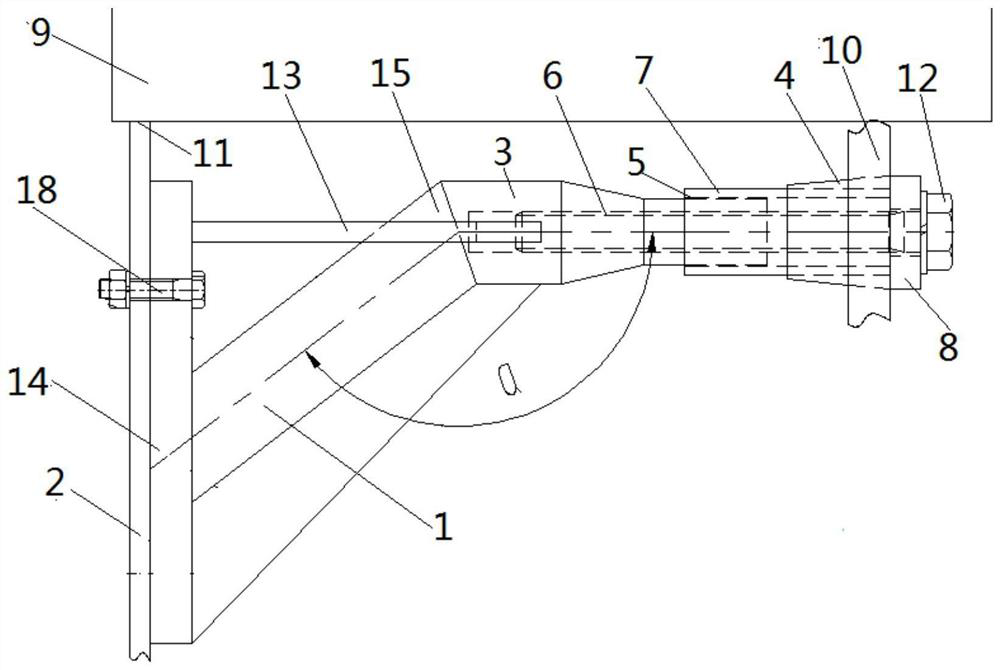
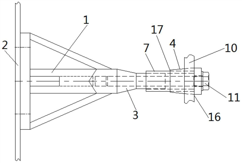
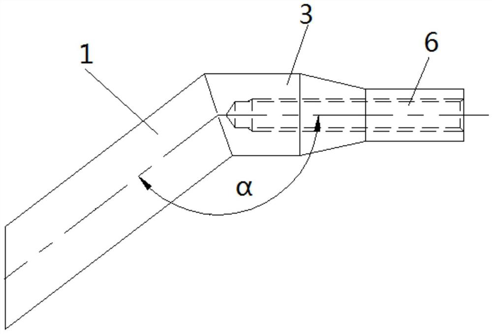
[0023] Below with reference to the accompanying drawings, through the description of the embodiments, the specific embodiments of the present invention, such as the shape, structure, mutual position and connection relationship between the various parts, the role and working principle of the various parts, etc., will be further described. Detailed instructions:

[0024] as attached figure 1 - attached Figure 4 As shown, the present invention is a speed reducer fixing device, the speed reducer fixing device includes a device bracket 1, one end of the device bracket 1 is connected to the reducer frame 2, and the other end of the device bracket 1 is provided with a connecting part 3, The connecting part 3 is provided with an external threaded part 5, and the connecting part 3 is provided with a threaded hole 6 at one end away from the device bracket 1, and one end of the casing part 7 is sleeved on the external threaded part 5 of the device bracket 1 through the internal thread ...


PUM


Abstract

The invention provides a speed reducer fixing device applied to the technical field of speed reducers of steel billet continuous casting withdrawal and straightening machines. One end of a device support (1) of the speed reducer fixing device is connected with a speed reducer rack (2), the other end of the device support (1) is provided with a connecting part (3), the connecting part (3) is provided with an external thread part (5), a threaded hole (6) is formed in the end part of one end, far away from the device support (1), of the connecting part (3), one end of a sleeve part (7) is sleevedon an external thread part (5) of the device support (1) through an inner thread part, the other end of the sleeve part (7) is provided with a flange part (8), the sleeve part (7) is sleeved with a wear-resistant buffering sleeve (4), and a speed reducer lifting lug (10) of a speed reducer (9) sleeves the wear-resistant buffering sleeve (4). The speed reducer fixing device can be used for conveniently and reliably reinforcing the speed reducer, so that the equipment stability is improved, the vibration damage of the speed reducer is reduced, and the speed reducer and the motor are prevented from swinging with relatively large amplitude.

Description

technical field [0001] The invention belongs to the technical field of reducer for billet continuous casting drawing and leveling machine, and more specifically relates to a fixing device for reducer. Background technique [0002] In the prior art, the steel billet of the continuous casting drawing and leveling machine is cut by the fire cutter, and then transported out through the billet discharge and conveying roller table. The billet moves in the roller table mainly by the rotation of the roller. The roller is connected with a reducer and a motor. The method is: the motor rotates to drive the reducer to rotate, and then the reducer drives the roller to rotate. The reducer has the following defects during use: 1. When the steel billet walks in the roller table, it has a large impact on the rollers, causing the rollers to vibrate, which in turn drives the reducer to vibrate. This vibration is not good for the fixation of the reducer, and often leads to loosening of the redu...

Claims


Application Information

Patent Timeline
Patent Type & Authority Patents(China)
IPC IPC(8): B65G13/06B22D11/12
CPCB22D11/1226B65G13/06
Inventor 王伟峰戴本俊高振波
Owner MAANSHAN IRON & STEEL CO LTD
Why Eureka
Try Eureka