Manipulator capable of rotating quickly and accurately

A manipulator, precise technology, applied in the direction of conveyor objects, transportation and packaging, etc., can solve the problems of increasing work difficulty, winding friction on both sides, slowing down of rotation speed, etc.

Inactive Publication Date: 2021-02-05
刘金海
View PDF6 Cites 0 Cited by
  • Summary
  • Abstract
  • Description
  • Claims
  • Application Information

AI Technical Summary

Problems solved by technology

[0004] The purpose of the present invention is to provide a manipulator that can rotate quickly and accurately, so as to solve the problem that the output wire of the existing manipulator in the above background technology cannot be supported when it is in use, which will easily cause winding friction on both sides, affect the output signal transmission, and affect the work. The rotation speed becomes slower, which increases the difficulty of the work

Method used


Image

  • Manipulator capable of rotating quickly and accurately
  • Manipulator capable of rotating quickly and accurately
  • Manipulator capable of rotating quickly and accurately

Examples


Embodiment 1

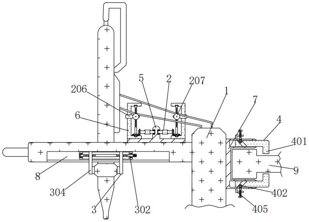
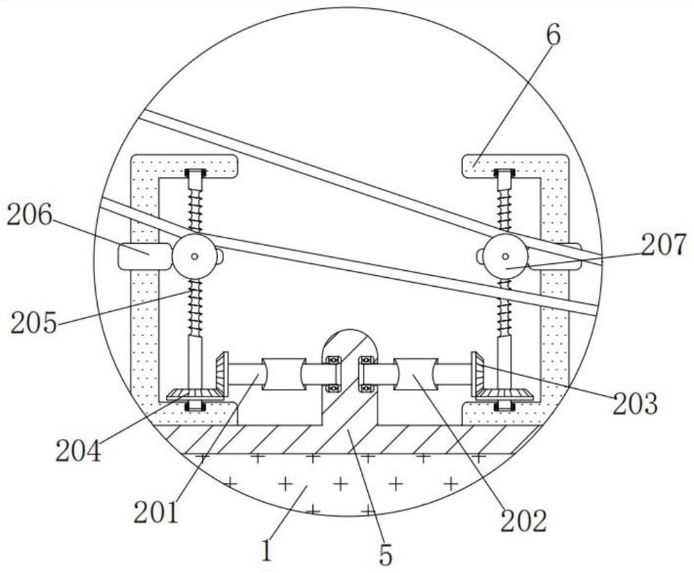
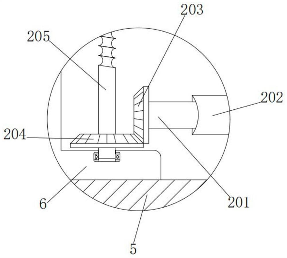
[0034] A manipulator capable of fast and precise rotation, comprising a manipulator 1, a convex plate 5 is fixedly connected to the right side of the top of the manipulator 1, square frames 6 are fixedly connected to the left and right ends of the top of the convex plate 5, and the left and right sides of the convex plate 5 are respectively Support mechanism 2 is installed, and support mechanism 2 comprises cross bar 201, rubber sleeve 202, first gear 203, second gear 204, threaded rod 205, cover plate 206 and sheave 207, and the inboard of two cross bars 201 is connected with convex respectively. The left and right sides of the plate 5 are rotated and connected, and the cross bar 201 is forced to rotate through the bearings on the left and right sides of the convex plate 5. The outer walls of the two cross bars 201 are fixedly connected to the inner walls of the rubber sleeves 202, and the rubber sleeves 202 are convenient for rotating the cross bar. 201, the outer sides of th...

Embodiment 2

[0037] As an option, see figure 1 with 4 , a manipulator that can rotate quickly and accurately, a fixing mechanism 3 is installed inside the chute 8, and the fixing mechanism 3 includes a long plate 301, a stud 302, a handle 303, a vertical plate 304 and a short plate 305, and the outer wall of the long plate 301 Sliding and clamping with the inner wall of the chute 8, the long plate 301 is forced to slide left and right through the inner wall of the chute 8, and the left and right sides of the inner wall of the long plate 301 are respectively connected to the left and right sides of the double-ended stud 302, and the double-ended stud 302 is forced to rotate through the bearings on the left and right sides of the inner wall of the long plate 301. The right end of the double-ended stud 302 is fixedly connected to the left side of the handle 303. The handle 303 is convenient to rotate the double-ended stud 302, and the double-ended stud 302 The left and right sides of the out...

Embodiment 3

[0040] As an option, see figure 1 , 5And 6, the manipulator that can rotate quickly and accurately. The right side of the manipulator 1 is fixedly connected with a concave plate 7, and a connecting mechanism 4 is installed in the grooves on the upper and lower sides of the front of the concave plate 7. The connecting mechanism 4 includes a curved plate 401 and a roller 402. , vertical plate 403, bolt 404 and bracket 405, the outer wall of the curved plate 401 is slidingly engaged with the inner wall of the groove above the front of the concave plate 7, the curved plate 401 is forced to slide left and right through the groove above the front of the concave plate 7, and the curved plate 401 The groove on the left side of the front is slidingly engaged with the outer wall of the round wheel 402. The round wheel 402 slides up and down through the front left groove of the curved plate 401 under force. The front of the round wheel 402 is connected to the inner wall of the vertical p...


PUM


Abstract

The invention discloses a manipulator capable of rotating quickly and accurately. The manipulator capable of rotating quickly and accurately comprises a manipulator body, a protruding plate is fixedlyconnected to the right side of the top of the manipulator body, each supporting mechanism comprises a transverse rod, a rubber sleeve, a first gear, a second gear, a threaded rod, a sleeve plate anda grooved wheel, and the inner sides of the two transverse rods are rotationally connected with the left side and the right side of the protruding plate correspondingly. The grooved wheels are controlled by the supporting mechanisms to move up and down to support a wire, winding friction is avoided, signal transmission is guaranteed, rapid and accurate rotation work is guaranteed, the work difficulty is reduced, the wire is supported by the supporting mechanisms, damage caused by winding friction is avoided, a wire core is prevented from leaking out, the service life is prolonged, shaking in use is prevented, the article fixing effect is ensured, and falling risk is prevented. Connecting mechanisms control bent plates to move towards the left side to fix a connecting block, fixing points are increased, deviation of the manipulator is prevented, loosening is avoided, practicability is improved, and popularization is facilitated.

Description

technical field [0001] The invention relates to the technical field of fast and precise rotating manipulators, in particular to a fast and precise rotating manipulator. Background technique [0002] It is an automatic operation device that can imitate certain action functions of the human hand and arm to grab, carry objects or operate tools according to a fixed program. The manipulator is the earliest industrial robot and the earliest modern robot. [0003] When the existing manipulator is in use, the wires at the output end cannot be supported, and it is easy to cause winding friction on both sides, which affects the output signal transmission, affects the work, causes the rotation speed to slow down, increases the difficulty of work, and the long-term winding friction is easy to cause damage and leak internal wires. core, which shortens the service life, and the manipulator is easy to shake when it is transported, which affects the fixing effect of the item and is prone to...

Claims


Application Information

Patent Timeline
Patent Type & Authority Applications(China)
IPC IPC(8): B65G47/90
CPCB65G47/90
Inventor 刘金海
Owner 刘金海
Why Eureka
Try Eureka