Image forming apparatus and method, program and computer readable medium

An imaging device and program technology, applied in image communication, electrography, optics, etc., can solve the problem that it is difficult to determine the priority of application programs, and achieve the effect of stable operation

Inactive Publication Date: 2007-02-28
RICOH KK
1 Cites 4 Cited by

AI-Extracted Technical Summary

Problems solved by technology

In addition, it is difficult for the general us...

Method used

[0140] As mentioned, according to the compound machine 100 of this embodiment, by using the operation panel as shown in FIGS. 9-36, the copy process, the install process, and the uninstall process can be easily operated. Since the respective application information is displayed on the operation panel, the user can sequentially select screens according to the displayed application information. Therefore, easy handling can be ...

Abstract

Provided is an image forming apparatus and method, program and computer readable medium in which a plurality of applications can be installed. The image forming apparatus includes: information obtaining part, obtaining the required resource information and the available resource information for executing the applications in the image forming apparatus; and an operation restricting part, comparing the required resource information and the available resource information and executing the operation restricting course on the applications based on the comparative result.

Application Domain

Electrography/magnetographyPictoral communication

Technology Topic

Multiple applicationsResource information +1

Image

  • Image forming apparatus and method, program and computer readable medium
  • Image forming apparatus and method, program and computer readable medium
  • Image forming apparatus and method, program and computer readable medium

Examples

  • Experimental program(8)

Example

[0075] (First embodiment)
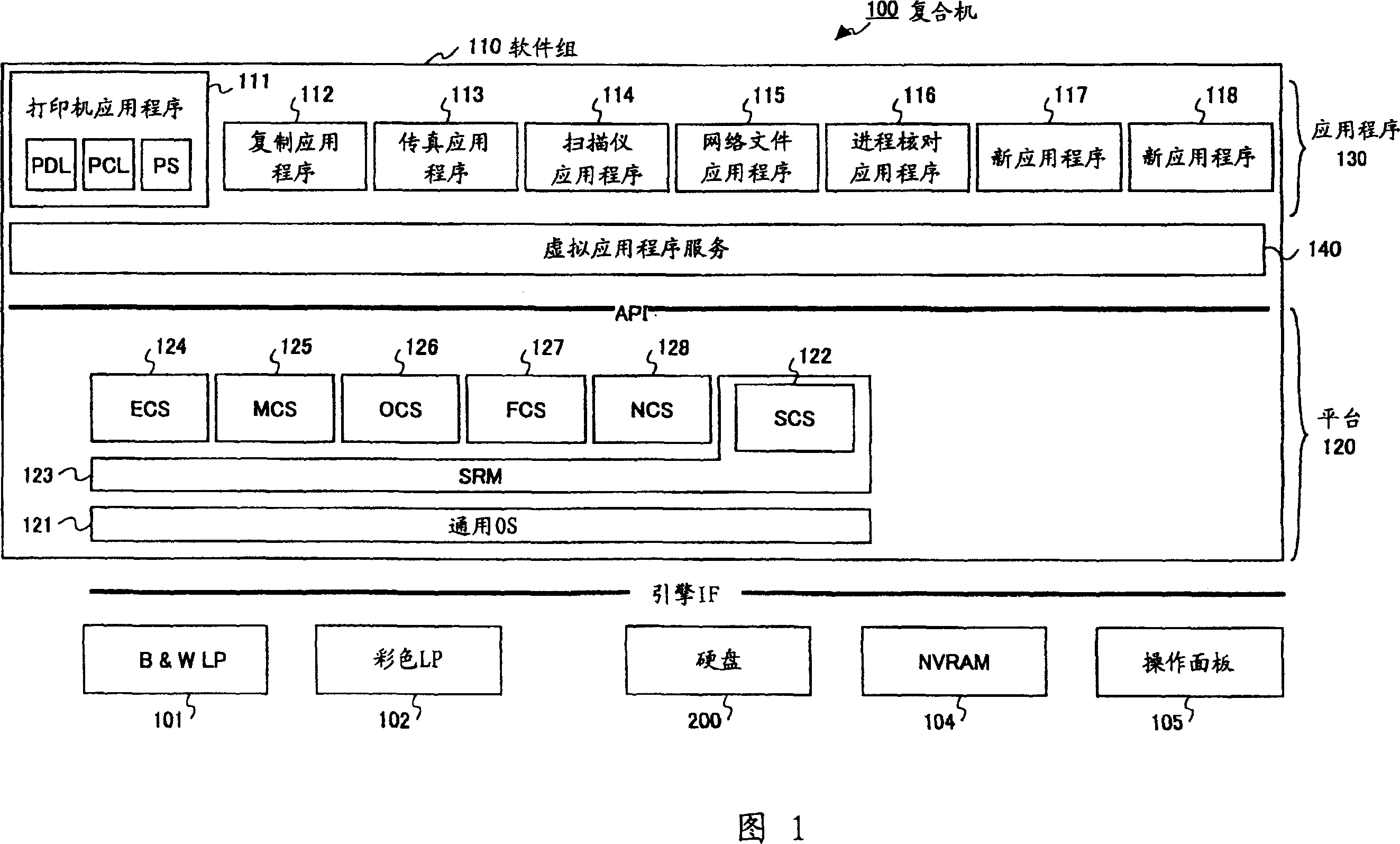
[0076] Fig. 1 is a block diagram of an image forming apparatus (hereinafter referred to as a compound machine) according to a first embodiment of the present invention. As shown in FIG. 1, the multifunction machine 100 includes a hardware resource and a software group 110. Hardware resources include black and white line printer (B&W LP) 101, color laser printer 102, and hardware resources 103, such as scanners, fax machines, hard disks, memory (RAM, NV-RAM, ROM, etc.), and network interfaces . The software group 110 includes a platform 120, an application program 130, and a virtual application service 140 (hereinafter referred to as VAS).
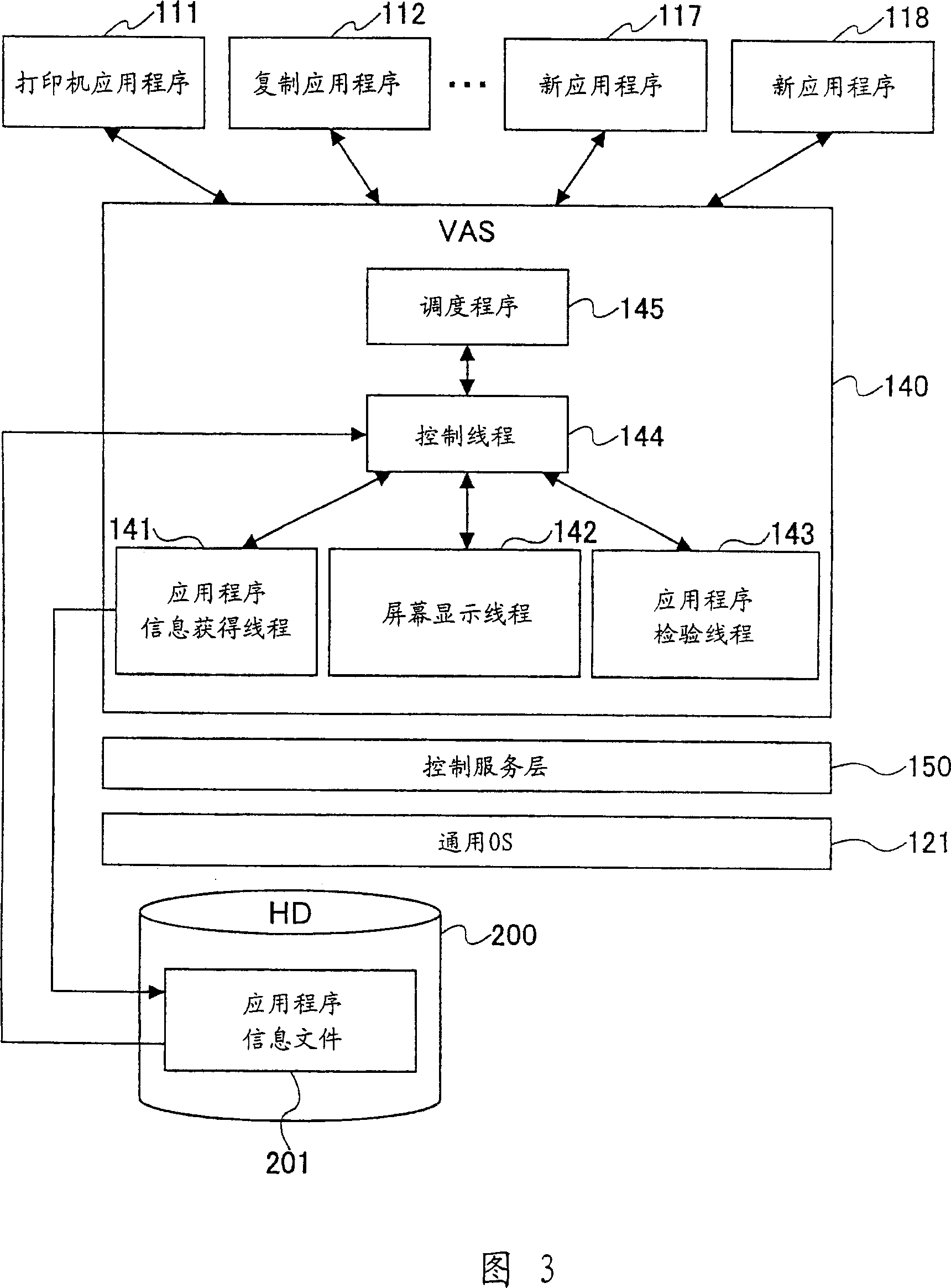
[0077] The VAS 140 works as a client process for controlling services and works as a server process for application programs. Before the VAS 140 executes the installation process, it obtains application program information, wherein the installation process is executed to make the application program runnable in the multifunction machine. Then, the VAS 140 generates an application information file in the hard disk 200. For example, the information obtained is product information. Product information includes product ID, manufacturer name, application name, version, contact address (phone number), required resources, confirmation about installation, and corresponding application information. The product information can be included in the execution file of the application program, or can be obtained by reading the file via the network, for example. In addition, when the product information has been stored in the hard disk 200, the NVRAM 104, the application information table 106, etc., the product information can be obtained by reading one of them.
[0078] The application program information included in the application program execution file can be obtained by the VAS 140 by temporarily running the application program in order to start the inter-process communication between the VAS 140 and the application program.
[0079] By temporarily running the application, the VAS 140 can obtain the application information in the execution file of the application by using the inter-process communication between the VAS 140 and the application.
[0080] For example, application programs can be copied from PC cards, IC cards, SD cards, etc. to the hard disk. Then, an installation process is performed on the application program, where the application program is set to be runnable. In this embodiment, before executing the installation process, the VAS obtains application information about the application, so that the VAS can determine whether the application can be installed in the multifunction device. Whether the application can be installed depends on whether the application makes the compound machine unstable or stops its operation due to lack of resources or version inconsistency. Before installing the application, the reason for checking the application is that it is meaningless to install an inoperable application, and if the application is run by mistake, the application may adversely affect the operation of the multifunction machine.
[0081] The platform 120 includes a control service for interpreting process requests from applications and issuing query requests for hardware resources, and a system resource manager (SRM) for managing one or more hardware resources and arbitrating query requests from the control service. ) 123 and general OS 121.
[0082] The control service includes multiple service modules, which are System Control Service (SCS) 122, Engine Control Service (ECS) 124, Memory Control Service (MCS) 125, Operation Panel Control Service (OCS) 126, Fax Control Service (FCS) 127 , Network Control Service (NCS) 128. In addition, the platform 120 has an application program interface (API) that can receive process requests from the application program 130 by using predetermined functions.
[0083] The general OS 121 is a general operating system, such as UNIX, and can execute each software part of the platform 120 and the application program 130 as a process.
[0084] The process of SRM 123 is used to perform system control and to perform resource management with SCS 122. The process of SRM 123 comes from the use of engines, such as scanner components and printer components, memory, HDD files, main I/Os (Centronics I/F, network I/F, IEEE1394 I/F, RS232C I/F, etc.) The upper-level request of hardware resources completes arbitration and execution control.
[0085] More specifically, the SRM 123 determines whether the requested hardware resource is available (whether it is not used by another request), and when the requested hardware resource is available, informs the upper layer that the requested hardware resource is available. In addition, the SRM 123 performs scheduling on the hardware resources used according to the request from the upper layer, and directly executes the process corresponding to the request (for example, paper transfer and imaging of the printer engine, storage space allocation, file generation, etc.).
[0086] The process of SCS 122 performs application management, control operation part, display system screen, LED display, resource management and interrupt application control.
[0087] The process control hardware resources of ECS 124 include engines for black and white laser printer (B&W LP) 101, color laser printer (Color LP) 102, scanners, fax machines, etc. The MCS125 process obtains and releases the image memory area, uses a hard disk device (HDD), and compresses and expands image data.
[0088] The process of FCS 127 provides APIs for sending and receiving faxes from each application by using the PSTN/ISDN network, registration/reference of various types of fax data managed by BKM (backup SRAM), and fax reading , Fax receiving and printing, and mixed sending and receiving.
[0089] NCS128 is a process used to provide services usually used for applications that require network I/O. NCS128 distributes the data received from the network according to the protocol to the corresponding application, and when sending the data to the network, it acts as an intermediary between the application and the network. More specifically, the NCS128 process includes the server data adaptive authentication monitor (server daemon) of the protocol, such as ftpd, httpd, 1pd, snmpd, telnetd, smtpd and client functions.
[0090] The OCS 126 process controls the operation panel of the device used to transfer information between the operator (user) and the control unit of the machine. In the compound machine 100 of the present invention, the OCS 126 includes an OCS process part and an OCS function library part. The OCS process partly obtains the key event, which means that the key is pressed from the operation panel and the key event function corresponding to the key event is sent to the SCS 122. The OCS function library registers drawing functions and other functions used to control the operation panel. The drawing functions are used to output different images to the operation panel according to the request from the application or from the control service. The OCS function library is dynamically linked to each module of the application and control service. All OCS 126 can be constructed as processes, or can be constructed as OCS libraries.
[0091] The application program 130 includes a printer application program 111 (the printer application program is an application program for a printer, with page description language (PDL) and PCL and appendix (PS)), a copy application program 112, a fax application program 113, and a scan The scanner application 114, the network file application 115, the progress check application 116, and the new applications 117 and 118 of the instrument. These application programs are application programs dedicated to the compound machine 110. When the application is running, the application sends an application registration request message with a process ID to the VAS 140. Then, VAS 140 performs a registration process for the application.
[0092] Inter-process communication is performed between the process of the application 130 and the process of the control service, in which functions are called, return values ​​are sent, and messages are sent and received. By using inter-process communication, user services for imaging processes such as copying, printing, scanning, and sending faxes can be realized.
[0093] As described above, the compound machine 100 of the first embodiment includes a plurality of application programs 130 and a plurality of control services, and each of these functions as a process. In each process, one or more threads are spawned and threads are executed in parallel. The control service provides public services for the application 130. Provides user services related to image formation such as copying, printing, scanning, and sending faxes and executes these processes in parallel, executes these threads, and executes inter-process communication. The third-party vendor can develop an application program for the multifunction machine 100, and can execute the application program in the application layer on the control service layer of the multifunction machine 100. The new applications 117 and 118 shown in Fig. 1 are examples. New applications can be added or deleted one by one.
[0094]FIG. 2 shows an example of the hardware configuration of the multifunction machine 100.
[0095] The compound machine 100 includes a controller 160, an operation panel 175, a fax control unit (FCU) 176, and an engine part 177 dedicated to hardware resources such as a printer for imaging processing. Controller 160 includes CPU161, system memory 162, north bridge (NB) 163, south bridge (SB) 164, ASIC166, local memory 167, HDD168, network interface card (NIC) 169, SD card slot 170, USB device 171, IEEE1394 device 172, and Centronics173. The memories 162, 167 may include, for example, RAMs and/or ROMs. The FCU 176 and the engine part 177 are connected to the ASIC 166 in the controller via the PCI bus 178. The CPU 161 executes application programs and executes control services installed in the multifunction machine 100 and the like by reading data from the RAM.
[0096] 3 is a block diagram showing the structure of the VAS 140 and the relationship between the VAS 140, each application program, the control service layer 150, and the general OS 121.
[0097] The process of the VAS 140 includes a scheduler 145, a control thread 144, an application information obtaining thread 141, a screen display thread 142, and an application verification thread 143. The screen display thread 142 generates an operation screen on the operation panel. The application verification thread 143 verifies whether the application can be installed according to the obtained application information.
[0098] The scheduler 145 monitors the reception of messages from the application 130 or from the control service. The scheduler 145 sends the process request to the control thread 144, the application information obtaining thread 141, the screen display thread 142, and the application verification thread 143 according to the received message.
[0099] The control thread 144 requests the threads 141-143 in order to execute the application information obtaining process, the screen display process, and the application verification process. In the application program checking process, the VAS checks whether the application program adversely affects the compound machine 100 if the application program is run. For example, VAS 140 obtains application information of which application is requested to be installed and obtains application information of an application that has been installed. Then, the VAS can check the resource or version of the application in order to check whether the application adversely affects the multifunction machine. At that time, the screen display thread 142 displays the application information of the application on the operation panel 105 by using the application information in the application information file stored in the hard disk 200. Therefore, the user can understand the status of the application to be installed. Therefore, even when the application is determined to be uninstallable, the user can understand the reason for the determination.
[0100] In addition, the control thread 144 controls the installation process and the uninstallation process, where the installation process is executed when the application program is determined to be installable, and the uninstallation process is executed when the application program becomes unnecessary.
[0101] When the application information obtaining thread 141 receives a process request from the control thread 144, the application information obtaining thread 141 temporarily runs an uninstalled application to start the inter-process communication between the VAS and the application, and obtains the application from the application information. Regarding the installed application, the application information is obtained through inter-process communication by running the application. The obtained application information is stored in the hard disk 200 as an application information file 201. Record the application information as a record for each application.
[0102] The program of VAS 140 can be provided as part or all of SDK (software development kit). The program can be provided as a recording medium, such as an executable file or an installable file in a CD-ROM or FD. In addition, VAS 140 program files can be provided via the network.
[0103] FIG. 4 shows the relationship between the VAS 140 and the hard disk 200 storing application information, the application table 106 and the NVRAM 104. As shown in FIG. 4, the product information stored in the hard disk 200 is managed for each application. By specifying the product ID, the application information corresponding to the product ID can be specified. In addition, the hard disk 200 stores data of the application programs A and C copied in the multifunction machine 100. Install application B from the IC card. "F" indicated by a dotted line represents an execution file group existing in a patch file (patch).
[0104] The NVRAM 104 is a non-volatile memory that can store the memory contents even if the power is turned off. The NVRAM 104 stores the product ID, operation information, and other information for each application. When the application is installed, information about the application is recorded in the NVRAM 104. In addition, the operation information indicates whether the corresponding application will be run when the power of the multifunction device is turned on.
[0105] The application information table stores information about applications as table data. By specifying the product ID of application A, the application name, version, and installation attributes can be obtained from the table, and information can be displayed on the operation panel.
[0106] FIG. 5 shows the entire process for executing the installation process or the uninstallation process in the compound machine 100. FIG. 6 is a flowchart showing a subroutine of the application information obtaining process in step S411 in FIG. 5.
[0107] In step S401 of FIG. 5, the scheduler 145 requests the application information obtaining thread 141 to obtain the application information of the application via the control thread 144. The application information obtaining thread 141 generates an application information file 201 by executing the application information obtaining process shown in FIG. 6.
[0108] Then, the control thread 144 reads the application information from the application information file 201, and generates an operation screen in step S402 to display the operation screen on the operation panel. The display shows the application name, version, resource information, etc. used for each application. In addition, the display indicates whether the application can be installed. By displaying this screen, the user can understand the status of the application, and the user can select items on the screen to enter the installation process.
[0109] After the user selects some items, the compound machine 100 waits for user input in step S403, and determines whether there is a user request in step S404. The user request is an application installation request or an application uninstallation request. If the installation of the application is requested and the request is allowed, in step S405, the information is registered to the NVRAM 104 shown in FIG. If the request is for uninstalling the application, in step S406, the application information is deleted from the NVRAM 104 shown in FIG. 4.
[0110] Fig. 6 is a flowchart showing an operation for obtaining application information. Since the application information cannot be obtained if the application is not running, the VAS 140 temporarily runs the application in step S501. Then, the VAS 140 can obtain application information by requesting required information from the application by using inter-process communication. According to this embodiment, the VAS 140 obtains the product ID in step S502 and accesses the NVRAM 104 so that the VAS 140 can determine whether the application has been registered in step S503.
[0111] If the application is not registered in the NVRAM 104, the VAS 140 determines whether there is a product information file in step S504. If there is no product information file, the VAS 140 obtains application information from the application by using inter-process communication in step S505. Then, the product information file is generated in step S506, and the VAS 140 determines whether the application can be installed in step S507. In step S508, the VAS 140 reflects the determination result on the product information. For example, the determination is performed by comparing the resource information obtained from the application program and used by the application program with the available resource information of the system of the multifunction peripheral.
[0112] In step S509, it is determined whether the application can be installed according to the comparison result. When the product information file exists in step S504, in step S510, the application information is obtained from the product information file. After obtaining the information for determining whether the application can be installed in step 511, it is determined whether the application can be installed in step S509.
[0113] If the application can be installed in step S509, an installable flag is set in step S512, and in step S516, the flag is written into the application information table. When the application cannot be installed, a non-installable flag is set in step S513, and the flag is written into the application information table in step S516. If in S503, the product information has been registered in the NVRAM 104, in step S514, the application information is obtained from the NVRAM 104, and the installation flag is set in step S515, and in step S516, the flag is written into the application information table.
[0114] If the above process is not completed for each application, the step returns to step S501 and the above process is repeated.
[0115] According to the compound machine of this embodiment, since application information for all applications is obtained, the status of the application can be understood.
[0116] Next, temporarily running the application will be described. The temporary operation is different from the normal operation of the application program, in which the independent resources of the multifunction machine are used (the operation that generates the function (function) required by the application program is called "normal operation"). During temporary operation, the application does not obtain resources, such as the storage area required when the application is normally operated. In temporary operation, the application only performs communication with the VAS 140 process, where the application provides information about the application to the VAS. When the communication between the application and the VAS is terminated, the process of the temporarily running application is terminated. In addition, the temporarily running function of the application program has nothing to do with the normal function of the application program, and is common to the application program of the multifunction machine of this embodiment. Therefore, for example, by providing a program template including a temporarily running function to a vendor, the vendor can easily develop an application program applicable to a multifunction machine by using the program template. To include application information in the application, for example, the vendor generates an include file that includes the application information, and when compiling the application, the include file is included in the application.
[0117] By providing temporary running functions for the application, the application can provide the application information to the VAS 140 without normal operation, so that the VAS 140 can verify the application.
[0118] FIG. 7 shows an example of a program description (main function) of an application program including a temporarily running function. The description can be provided as a program template. As shown in Figure 7, the argument (-v) determines whether to run the application temporarily or normally. Therefore, when the VAS 140 runs the application, it can easily select one of normal operation and temporary operation. That is, when the temporary operation is selected by using the argument (-v), the application is temporarily operated to inform the application information. If you do not choose to run temporarily, run the application normally so that the internal operations of the application can be performed.
[0119] The VAS 140 obtains information from the application and determines whether the application can be installed in this embodiment. Instead of this process, the process shown in FIG. 8 can be adopted. In the process shown in FIG. 8, when the VAS 140 determines that the application can be installed, the VAS 140 in step S601 asks whether the application can actually be installed. If in step S602, the application informs the VAS 140 that the application can be installed, in step S603, the VAS 140 executes the installation process for the application.
[0120]Between step S601 and step S602, the application can obtain system information (resource data or configuration data) from the VAS 140, and the application can determine whether the application itself can be installed according to the system information.
[0121] In this embodiment, VAS 140 obtains application information from the execution file of the application. Instead of this method, for example, VAS 140 may also obtain application information from a file including the application information. By storing the file in the server, the VAS 140 can obtain the application information via the network.
[0122] In addition, the display screen on the operation panel and the verification application can be executed by programs other than the VAS 140, respectively.

Example

[0123] (Second embodiment)
[0124] In this embodiment, an example of the screen displayed by the screen display thread 142 can be described in more detail.
[0125] 9-36 show the state transition of the operation screen displayed on the operation panel 105. Fig. 9 shows the verification screen of the initial setting screen. Figure 10-16 shows the screen used for file copy operations. Figure 17-28 shows the screen used for installation operations. Figures 29-36 show the screens used for the uninstall operation.
[0126] In the authentication screen shown in Figure 9, enter the user ID and password. After inputting them and pressing the OK button 210, the desired mode can be selected. In this embodiment, before installing the application, the application is copied in the multifunction device 100. As shown in FIG. 10A, a file copy screen is displayed, and the storage location of the file to be copied is selected. In this embodiment, the destination can be selected from the memory card 211, the SD card 212, and the via network 213. As shown in FIG. 10B, when via network 213 is selected and the OK button 216 is pressed, the download screen shown in FIG. 11A or the copy screen shown in FIG. 11B is displayed. The download screen is used to download the application by using the Web. The copy screen is used to copy applications by using the LAN network. When the cancel button 215 is pressed in FIG. 10B, the screen returns to FIG. 10A. When the EXIT button 214 is pressed, the screen returns to FIG. 9 where the verification screen is not shown.
[0127] FIG. 12A shows a situation where the memory card 211 is selected. FIG. 12B shows a situation where the SD card 212 is selected. When the OK button is pressed, the screen changes to FIG. 13A displaying the file list generation waiting screen. When the CANCEL button 221 is pressed, the screen returns to FIG. 10A. FIG. 13B shows the file list 222.
[0128] Fig. 14A shows a screen for selecting SimpleCopy225 from the file list. Fig. 14B shows a screen where SimplePrint223 is additionally selected. When the OK button 216 is pressed in FIG. 14A, the screen changes to the waiting screen shown in FIG. 15A. If there are identical files, a warning screen as shown in FIG. 15B is displayed, in which a confirmation for overwriting is displayed. When the file copying ends, the screen shown in Fig. 16A is displayed. At this point, copy the application program to the multifunction machine.
[0129] Fig. 17 shows an example of the installation operation screen. When the installation flag is selected, the above application information is obtained.
[0130] FIG. 17A shows such things as "registration allowed", "registration not allowed" and "registration". "Registration" means to record application information in NVRAM by performing the installation process. When the VAS 140 accesses the NVRAM, the VAS 140 can determine whether the application has been registered.
[0131] When the VAS 140 determines that the application cannot be installed in the compound machine 100 due to some reasons, "Registration is not allowed" is displayed. For example, when the resource used by the application program is not provided on the multifunctional machine 100, it is determined that the application program cannot be installed.
[0132] "Unregistered (registration allowed)" means that although the application can be installed, the installation process has not been performed.
[0133] As shown in FIG. 17B, when the installable program SimpleCopy235 is designated, the field of the application program flashes. On the other hand, as shown in FIG. 19A, when it is specified that registration of the application 234 is not permitted, the screen changes to FIG. 19B, and a message indicating that the application cannot be installed and the reason is displayed. When the VAS 140 obtains the application information, it stores the information for displaying the message in the multifunction machine.
[0134] In the screen shown in FIG. 17A, when the application program for installation is selected, the source medium (from which the application program is copied) and the destination medium (where the application program is installed after the application program is installed) can be displayed as shown in FIG. Existing medium). In this case, the destination can be selected. For example, as shown in FIG. 18, the application program copied in the SD card can be installed in the SD card.
[0135] When the application is selected to be installed, the screen changes from FIG. 20A to FIG. 20B, and a warning screen is displayed. When the installable application is selected, after the registration waiting screen 240 as shown in FIG. 21A is displayed, the registration end screen as shown in FIG. 21B is displayed. Then, the application registration (application installation) is ended. Therefore, as shown in FIG. 22, the number of installed applications is increased.
[0136] FIG. 23A shows another example showing installed applications and non-installable applications. From the situation of FIG. 23B, when no item is selected, the screen returns to FIG. 23A. As shown in FIG. 24A, a plurality of applications can be selected as applications to be installed. As shown in Fig. 24B, even if an application is selected, the selection can be cancelled.
[0137] As shown in FIG. 25A, when the uninstallable application is selected, as shown in FIG. 25B, a warning screen is displayed. As shown in FIG. 26A, when an installed application is selected, a warning screen as shown in FIG. 26B is displayed, in which a warning indicating that the setting value will be initialized is displayed. As shown in FIG. 27A, when the application is being registered, the screen changes to a waiting screen. Then, the completion result is displayed in Fig. 27B. Then, as shown in Figure 28, the name of the installed application is displayed.
[0138] Regarding the uninstallation process, a screen as shown in FIG. 29A is displayed. Fig. 29B shows a screen for selecting an application to be uninstalled. When an application that is not allowed to be uninstalled is selected, a warning screen as shown in FIGS. 30A-30B is displayed. When uninstallation is permitted, FIGS. 31A and 31B are displayed, and the uninstallation result is displayed as shown in FIG. 32.
[0139] Figures 33 and 34 are examples of uninstall screens when a key has been assigned to the application. As shown in FIG. 34A, when SimpleScan is selected, a screen as shown in FIG. 34B is displayed in which it is requested whether to release the key designation and uninstall the application. When OK is pressed, the screens shown in FIGS. 35A and 35B are displayed, and the uninstall result is displayed as shown in FIG. 36.
[0140] As mentioned, the compound machine 100 according to this embodiment can easily operate the copy process, installation process, and uninstall process by using the operation screen as shown in FIGS. 9-36. Since each application information is displayed on the operation panel, the user can sequentially select the screen according to the displayed application information. Therefore, easy operation can be achieved.
[0141] In the example shown in FIGS. 9-36, the compound machine 100 determines whether the application can be installed, and displays the determination result on the operation panel. However, the compound machine 100 can also be configured such that the compound machine 100 simply displays information necessary for determining whether the application can be installed so that the user can perform the determination. In this case, for example, the version information of the APIs used in the application and the version information of the APIs actually used in the multifunction machine are displayed. In addition, the amount of resources to be used by the application and the amount of available resources actually used in the multifunction machine can be displayed so that they can be compared.
[0142] The above series of screens can be displayed on a device, such as a PC connected to a multifunction machine via a network, and the installation process can be executed by the device.
[0143] In this case, the web file application 115 shown in FIG. 1 has Web server capabilities. The Java program, which is a part of the web file application 115, generates a series of screens and executes the installation process for the multifunction machine 100 and the like by using a so-called "servlet" method. The PC includes a web browsing program.
[0144] The structure of the web file application 115 is shown in FIG. 37. As shown in FIG. 37, the web file application 115 includes a web server 1151, a JVM (Java Virtual Machine) 1152, and a Java program 1153. The web file application 115 receives the request from the PC. Then, the web file application 115 executes the installation process and generates an HTML file and returns the HTML to the PC.
[0145] While the screen is displayed on the PC, the same screen is displayed on the operation panel of the multifunction machine, or only the screen is displayed on the PC. When the screen is displayed on the PC while the same screen is displayed on the operation panel, for example, the web file application 115 obtains drawing information from the OCS, converts the drawing information into HTML and sends the HTML.

Example

[0146] (Third embodiment)
[0147] Hereinafter, the third embodiment will be described. The functional structure of the compound machine 100 of the third embodiment is the same as that of the first embodiment. That is, the functional structure of the multifunction peripheral 100 of the third embodiment is shown in FIG. 1.
[0148] Regarding general personal computers, if multiple applications are run one by one, there is a possibility that the PC may hang due to lack of resources. On the other hand, regarding the compound machine 100 of the present invention, pre-installed applications, such as copy applications, cannot be suspended.
[0149] However, since the multifunction device 100 can install a new application developed by a third vendor or user, there is a situation where there is a lack of resources when multiple applications have been set to run and the run settings for the new application are executed. .
[0150] When the electric multifunction device 100 is powered on, the "operation setting" of the installed application to be executed is executed. That is, in the multifunction peripheral 100 of this embodiment, only the application is installed, and the application is not run. It is necessary to perform the operation settings for running the application on the application. By executing the operation setting, it means that the information of the running application is stored in the memory. Then, when power is supplied to the compound machine 100, the information is referred to in order to run the application.
[0151] The VAS 140 obtains information about resources to be used by the application program (also referred to as required resource information) from the application program, and generates a resource usage information file by using the information in the hard disk (HD 200). The text storage area size, the stack area size, and the stack area size are examples of information about resources to be used. The text storage area is a storage area for loading programs for each application. The accumulation area is a storage area where each application is dynamically saved. The stack area is an area reserved for storing arguments used for calling external modules by each application.
[0152] When developing an application, include information about the amount of resources required in the execution file of the application. Then, VAS 140 temporarily runs the application to obtain information by using inter-process communication.
[0153] In addition, by storing information about the resources used by the application in a file, by referencing the file, the VAS 140 can obtain required resource information.
[0154] In addition, if the application has actually been executed on the multifunction machine 100, the VAS 140 can obtain the required amount of resources by obtaining the resource usage record of the application.
[0155]The VAS 140 also obtains the amount of available resources in the multifunction machine 100 by subtracting the amount of resources that have been used by the application program and the system from the total amount of resources of the multifunction machine 100. For the amount of resources that have been used by application programs and system programs, use records recorded in the multifunction machine can be used. The amount of resources that have been used by application programs and system programs can be recorded in the resource usage information file, and the VAS 140 can refer to them.
[0156] When executing the operation setting for the application, the VAS 140 compares the amount of required resources for the application with the amount of available resources. When the amount of resources is lacking in the multifunction machine, the operation is restricted, that is, the operation setting for the application is not executed. In addition, if the application has a limited execution mode, the VAS 140 can set the application to press The limited execution mode runs, where the limited execution mode is, for example, a mode in which the application program is run by using a hard disk area instead of the storage area when the storage area is insufficient.
[0157] Not only when the operation setting is executed, but also when the application is actually running, resource checking and operation restriction can be executed.
[0158] FIG. 38 is a block diagram showing the structure of the VAS 140 of this embodiment, and the relationship among the VAS 140, the application program, the control service layer 150, and the general OS 121.
[0159] In the process of the VAS 140, the scheduler 144, the control thread 143, the resource usage information obtaining thread 1141, and the application running restriction thread 1142 operate.
[0160] The scheduler 144 monitors messages received from applications or control services, and sends process requests based on the messages.
[0161] In the case of actually running an application, when the dispatcher 144 receives an application execution request message from the control service, the dispatcher 144 sends the received application execution request message to the control thread 143. The control thread 143 sends the process request to the resource usage information obtaining thread 1141 and the application program execution restriction thread 1142.
[0162] In the case of executing the running setting, for example, the scheduler 144 sends a process request message to the control thread 143, and the control thread 143 sends the process request to the resource usage information obtaining thread 1141 and the application running restriction thread 1142.
[0163] The control thread 143 can determine whether to record the resource usage information for the installed application program by referring to the resource usage information file 1201.
[0164] Then, the control thread 143 obtains the resource use information from the resource use information obtaining thread, and sends the resource use information to the application running restriction thread 1142. The application program execution restriction thread 1142 may reference the resource usage information file 1201. The application program execution limit thread 1142 compares the amount of available resources with the amount of required resources. If the amount of required resources is greater than the amount of available resources, the application execution restriction thread 1142 executes the execution restriction process.
[0165] When the resource usage information obtaining thread 1141 receives a process request from the control thread 143, the resource usage information obtaining thread 1141 references the process structure (or u area 212) of the general OS 121 to obtain the size of the text storage area and the size of the heap area used by the application. And the size of the stack area. Then, the resource usage information obtaining thread 1141 generates a resource usage information file 1201 in the hard disk (HD) 200. Record the resource usage information for each application as a record. Instead, as described above, the resource usage information obtaining thread 1141 can obtain required resource information from the application program included in the execution file of the application program, and record the resource information in the resource usage information file 1201.
[0166] In addition, the resource usage information obtaining thread 1141 can obtain the amount of resources used by the current process from the process structure 211, where the amount of resources currently used is used to calculate the amount of available resources.
[0167] Instead of performing the above-mentioned processing by using threads, the VAS 140 may be constructed as one process.
[0168] FIG. 39 shows an example of a resource usage information file 1201 stored in the HDD 200. As shown in FIG. 39, the resource usage information file 1201 stores the text storage area size, the stack area size, and the stack area size for each application ID (also referred to as product ID).
[0169] The file can store the structure data of the compound machine 100, such as ADF. By doing so, the operation restriction can be executed based on the structure data. For example, if the compound machine 100 does not have an ADF, the application program that uses the ADF is restricted from running.
[0170] FIG. 40 shows an example of the process structure 211 referenced by the resource usage information obtaining thread 1141. As shown in FIG. 40, the process structure 211 includes a process ID (P-pid) for each process, a text storage area size, a heap area size, and a stack area size. When the process is executed, when the process ends, and when the process changes state, the process structure is updated by the general OS.
[0171] In addition, the resource usage information obtaining thread 1141 obtains the amount of resources used by the application program and system program that have been set by the process structure 211 to run, and calculates the amount of available resources by subtracting the amount of resources currently used from the total amount of resources of the compound machine .
[0172] When the application program execution restriction thread 1142 receives an operation request for a new application program, or receives an operation setting request, the application program execution restriction thread 1142 references the resource usage information file 1201 and obtains information about resources used by the new application program. In addition, the application program execution restriction thread 1142 obtains the amount of available resources from, for example, the resource usage information obtaining thread 1141. Then, the application running restriction thread 1142 compares them and determines whether the new application needs to be restricted from running.
[0173] In the case of the operation setting, when the application execution restriction thread 1142 determines that the application execution restriction is necessary, the application execution restriction thread 1142 displays the following warning screen.
[0174] In actual operation, when the application restriction thread 1142 determines that the application operation restriction is necessary, the application operation restriction thread 1142 sends an operation restriction request message to the application that sends the application operation request. When the application program operation restriction thread 1142 determines that the application program operation restriction is unnecessary, the application program operation restriction thread 1142 sends an operation request message to the application program in order to perform a normal operation process.
[0175] Fig. 41 shows a diagram of a screen displayed on the operation panel, in which the operation limit level is displayed by using a histogram. This screen is displayed when the operation setting is executed. The histogram shown in FIG. 41 represents the amount of available resources obtained by subtracting the resources used by the application programs and system programs pre-installed in the multifunction machine from the total amount of resources. That is, the figure truly shows how to divide the remaining resources in the new application. By using this screen, the user can truly determine how to divide the remaining resources in the new application. The histogram indicates the amount of resources to be used by the user application 221 that is set to be run first, and the amount of resources that will be used by the user application 222 that is set to run next. As for the user application 223 for which the operation setting has not been performed, the predicted resource amount is shown. In the example of FIG. 41, if the operation setting for the user application 223 is executed, the amount of resources reaches a dangerous level. Therefore, the execution setting of the user application 223 cannot be performed. In this screen, the operation restriction level is indicated by using colors, for example, safety (green), warning (yellow), and danger (red). In addition, in the dangerous position, the histogram flashes, or voice guidance or warning sound can be output.
[0176] Hereinafter, an example of the screen displayed on the operation panel will be shown. For example, each screen is displayed by the VAS 140.
[0177] Fig. 42 shows the operation setting screen in which the operation settings for "simple scanner" and "simpleprint" have been executed. As shown in the figure, the amount of storage used by "simple scanner" and "simple print" is shown in histogram 251.
[0178] Next, when "simple print" is selected to execute the run settings, as shown in Figure 43, the "simple print" part flashes for a few seconds. Then, the value of the histogram becomes 100% and the histogram flickers.
[0179] After that, the screens shown in Figs. 44 and 45 are displayed. Fig. 44 is a screen for suggesting selection of another application. By pressing the OK button, the screen returns to Figure 42. FIG. 45 is an example of a screen that can execute operation settings even when sufficient memory is not included in the multifunction device. When an application for which no key is specified is selected, the screen shown in Fig. 46 is displayed.
[0180] In the screen of FIG. 42, when "simple scanner" is selected and when the operation setting is ended, after the screen of FIG. 47, the screen shown in FIG. 48 is displayed. As shown in Figure 48, the histogram value is increased by the amount of storage used by the "simple scanner".
[0181] When the run settings for the application are released, the screen shown in Figure 49-53 is displayed. In the case of FIG. 49, when the "simple scanner" for releasing the operation setting is selected, as shown in FIG. 50, the "simple scanner" blinks. If you press OK, the screen shown in Figure 51 is displayed. Then, if the OK button is pressed, the screen shown in FIG. 53 is displayed via FIG. 52. As shown in Figure 53, the storage capacity of the simple scanner is reduced from the histogram.
[0182] The application program execution restriction process executed by the VAS 140 of the compound machine 100 will be described with reference to the flowchart of FIG. 54. FIG. 54 shows the process executed by the VAS 140 when the operation setting is executed.
[0183] When the VAS 140 receives the operation setting request for the application in step S1601, the VAS 140 checks whether there is resource usage information for the application by referring to the HD 200 in step S1602.
[0184] When the resource usage information file exists, the VAS 140 obtains the resource usage information from the resource usage information file 1201 in step S1603. If there is no resource usage information file in step S1602, VAS 140 generates a resource usage information file in step S1604. For example, the control thread 143 requests the resource usage information obtaining thread 1141 to generate a resource usage information file, so that the resource usage information obtaining thread 1141 generates a resource usage information file.
[0185] The process for generating the resource usage information file will be described later with reference to FIG. 56.
[0186] Next, in step S1605, the VAS 140 obtains the amount of available resources. In order to calculate the amount of available resources, by using system calls or service function calls, the resource amount of the application program for which the operation settings have been executed can be obtained from the process structure. The general OS provides system calls, and the control service layer 150 provides service functions. In addition, if the resource amount is included in the resource usage information file 1201, the resource amount can be obtained from the resource usage information file 1201.
[0187]Next, VAS 140 compares the amount of resources required and the amount of available resources used by the application requesting to run the setting in S1606. The application program execution restriction thread 1142 determines whether the required resource amount is greater than the required resource amount in step S1607. If the amount of required resources is greater than the amount of available resources, a screen as shown in FIG. 44 is displayed in step S1608. If the amount of required resources is not greater than the amount of available resources, the operation setting is normally performed in step S1609.
[0188] If the application has a mode to run the application by using the hard disk area instead of the storage area, a screen for asking the user whether to use the mode can be displayed. When the user selects this mode, the application is executed by using this mode. The VAS 140 can learn that the application has this mode by referring to the application information.
[0189] Fig. 55 is a flowchart for executing the execution restriction process when the application is running.
[0190] When the scheduler 144 receives an application program execution request message from the control service layer, the scheduler 144 sends a message with a process ID to the control thread 143. The control thread 143 determines in step S1701 whether the application requested to run is an application other than an already pre-installed application, such as a copied application, that is, whether the application requested to run is a new application. If the application program is a new application program in step S1702, the control thread 143 checks whether there is resource usage information for the application program by referring to the HD 200 in step S1703.
[0191] When there is a resource usage information file for the application, the control thread 143 obtains the resource usage information from the resource usage information file 1201, and sends the resource usage information to the application execution restriction thread 1142 in step S1704. If in step S1703, the resource usage information file does not exist, the control thread 143 requests the resource usage information obtaining thread 1141 to generate the resource usage information file, so that in step S1705, the resource usage information obtaining thread 1141 generates the resource usage for the new application. Information file 1201. After the file is generated, step S1704 is executed.
[0192] Next, the VAS 140 obtains the amount of available resources in step S1706.
[0193] Next, the VAS 140 compares the required amount of resources used by the new application for requesting to run with the amount of available resources in step S1707. In step S1708, the application program execution limit thread 1142 determines whether the required resource amount is greater than the available resource amount. If the required resource amount is greater than the available resource amount, in step S1709, a warning screen is displayed. If the application has a mode for running the application by using the hard disk area instead of the storage area, a screen for asking the user whether to use the mode can be displayed. When the user selects this mode, the application is executed by using this mode.
[0194] If the required amount of resources is not greater than the amount of available resources, the new application program is run normally in step S1710.
[0195] FIG. 56 shows a flowchart for explaining the operation of the VAS 140 when the resource usage information file is generated.
[0196] First, in step S1801, the VAS 140 temporarily runs the application program through which the VAS 140 wants to obtain resource information. Then, in step S1802, the VAS 140 obtains resource information from the application program by using inter-process communication. Then, in step S1803, the VAS 140 generates a resource usage information file 1201 by using the obtained resource information. FIG. 39 is an example of a resource usage information file in which the text storage area size, the heap area size, and the stack area size for each application ID are recorded.
[0197] If the application is already running and the actual record of the resource usage of the application is stored in the process structure 211, the VAS 140 can obtain the usage record without obtaining information from the application. By updating the resource usage information file using the actual record, the updated resource information can always be obtained, that is, the learning ability is provided. If the actual usage record is changed every time the record is obtained, the average or maximum value of the records can be used as the resource information recorded in the resource usage information file 1201.
[0198] In the case of generating the resource usage information file 1201 by using the process structure in the RAM 210, when the resource usage information obtaining thread 1141 receives the process ID, product ID, and resource usage information obtaining request message from the control thread 143, the resource usage information obtaining thread 1141 The process structure 211 is referenced, and the location of the block of the process ID of the application ID is searched. Then, the resource usage information obtaining thread 1141 obtains the resource usage information from the process ID block, and records the obtained information in the resource usage information file 1201 of the application ID.
[0199] According to the compound machine of this embodiment, it is possible to prevent the operation of the compound machine from being unstable due to lack of resources. In addition, new applications developed by users or third vendors can be executed safely.
[0200] In this embodiment, the VAS 140 executes the resource usage obtaining process and the application running restriction process for all the application programs 130. However, the VAS 140 can also be configured to cover part of the application. For example, the VAS 140 may only execute the resource usage information obtaining process and the application running restriction process for the new application programs 117 and 118.
[0201] In addition, in consideration of changing the resource usage of the new application, even if the required resource amount is somewhat smaller than the available resource amount, the VAS 140 can also perform operation restriction on the new application.

PUM

no PUM

Description & Claims & Application Information

We can also present the details of the Description, Claims and Application information to help users get a comprehensive understanding of the technical details of the patent, such as background art, summary of invention, brief description of drawings, description of embodiments, and other original content. On the other hand, users can also determine the specific scope of protection of the technology through the list of claims; as well as understand the changes in the life cycle of the technology with the presentation of the patent timeline. Login to view more.

Similar technology patents

Fuel Injection Valve For Internal Combustion Engine

InactiveUS20070272771A1large widthstable operation
Owner:BOSCH CORP

Fischer-Tropsch synthesis process based on fixed bed reactor

ActiveCN103691369AUniform bed temperaturestable operation
Owner:中科潞安能源技术有限公司

Classification and recommendation of technical efficacy words

Why Eureka
Try Eureka