
Thermal print head

A technology of thermal printing head and heating resistor, which is applied in printing and other directions, and can solve problems such as deviation of the resistance value of the heating resistor part 91

Inactive Publication Date: 2007-02-28
ROHM CO LTD
View PDF1 Cites 4 Cited by
  • Summary
  • Abstract
  • Description
  • Claims
  • Application Information

AI Technical Summary

Problems solved by technology

However, in the above-mentioned prior art, since the resistance value adjustment of the plurality of heating resistors 91 has large deviations due to the resistance value adjustment, it cannot meet the above-mentioned requirements, so there is still room for improvement in improving the quality of the printed image.

Method used


Image

  • Thermal print head
  • Thermal print head
  • Thermal print head

Examples


Embodiment Construction

[0022] Hereinafter, preferred embodiments of the present invention will be specifically described with reference to the drawings.

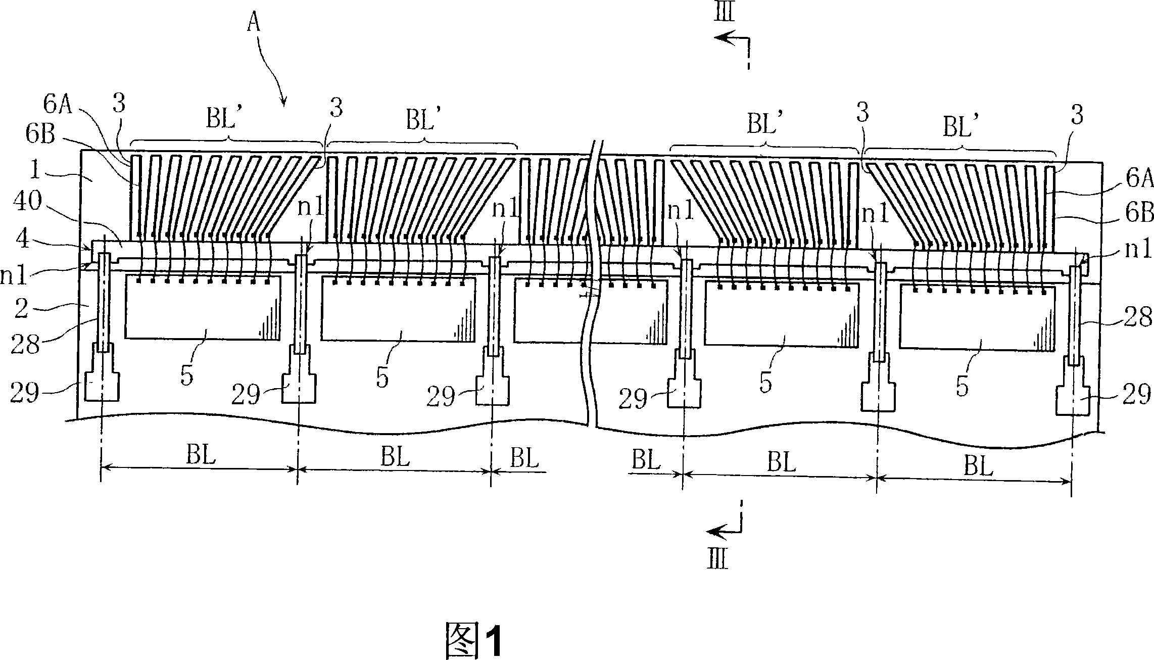
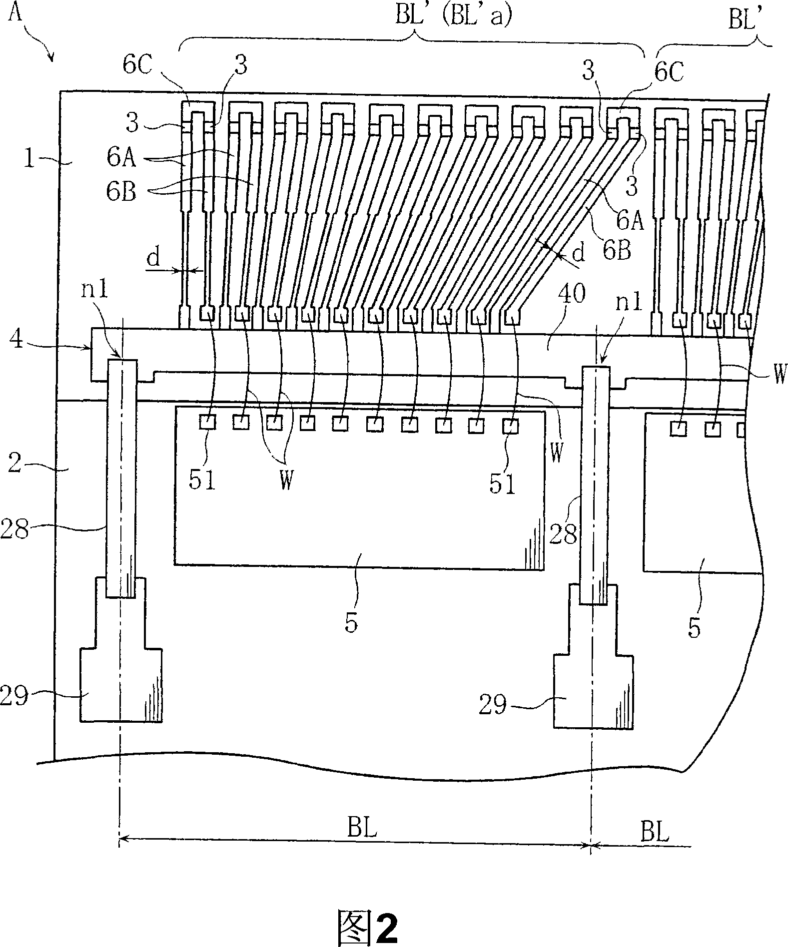
[0023] Figures 1 to 4 show an embodiment of the thermal printing head of the present invention. As shown in Figures 1 and 2, the thermal printing head A of this embodiment includes: a head substrate 1, a printing substrate 2, and a plurality of heating resistors. 3. The common wiring part 4 , the first to third lead wiring parts 6A to 6C, and the plurality of driver ICs 5 .

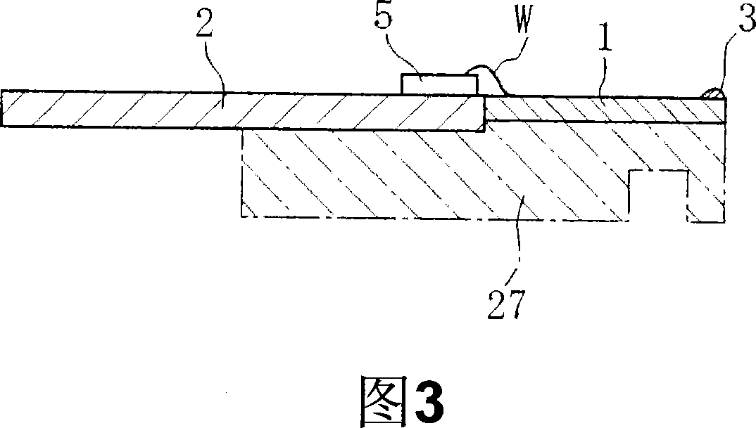
[0024] Both the head substrate 1 and the print substrate 2 are insulative flat plates that are long and rectangular in plan view. The head substrate 1 is made of alumina ceramics, for example. The print substrate 2 is made of, for example, glass epoxy resin. As shown in FIG. 3 , the head substrate 1 and the print substrate 2 are supported by a metal support member 27 and are aligned in the short direction (corresponding to the sub-scanning direction).

[0025] As shown in ...


PUM


Abstract

A thermal print head (A) includes a common wiring unit (4) and a plurality of heating resistors (3). The common wiring unit (4) is divided into a plurality of blocks (BL) arranged in the main scan direction and configured so that voltage is applied to the both ends of each of the blocks (BL) in the main scan direction. The heating resistors (3) are divided into a plurality of blocks (BL') corresponding to the blocks (BL) of the common wiring unit (4) and configured so that the resistance value is reduced from the both ends toward the center in the scan direction of each of the blocks (BL'). Thus, adjustment of the resistance value of the heating resistors is simplified and the print dot concentration irregularities are eliminated, thereby printing a high-quality image.

Description

technical field [0001] The present invention relates to a thermal print head used as a component of a thermal printer. More specifically, the present invention relates to a thermal print head capable of uniformizing the density of a plurality of print dots printed on a recording medium. Background technique [0002] Fig. 6(a) schematically shows an example of a conventional thermal print head. The illustrated thermal print head B has a structure in which a plurality of heating resistors 91 are arranged on a substrate 90 in the main scanning direction (left-right direction in the figure) and a linear portion 92a extending in the main scanning direction is provided. The common wiring part 92. One end of each heating resistor unit 91 is connected to the common wiring unit 92 through the first wiring unit 93A. In addition, the other end of each heating resistor unit 91 is connected to the driver IC 94 through the second wiring unit 93B and the wire w. A voltage is applied to ...

Claims


Application Information

Patent Timeline
Patent Type & Authority Applications(China)
IPC IPC(8): B41J2/345B41J2/35B41J2/355
CPCB41J2/35B41J2/345B41J2/355
Inventor 中西雅寿小畠忍
Owner ROHM CO LTD
Learn More