Voltage measuring device

Active Publication Date: 2014-11-27
HONDA MOTOR CO LTD
View PDF2 Cites 2 Cited by
  • Summary
  • Abstract
  • Description
  • Claims
  • Application Information

AI Technical Summary

Benefits of technology

[0026]On the other hand, compared with the choices available for the electrostatic capacitances of general-purpose capacitors, the choices available for the resistance values of general-purpose resistors are greater. Trimmer resistors, the resistance values of which are adjustable as desired, are also generally available. In add

Problems solved by technology

Furthermore, according to each of the above documents, since the capacitors must all be connecte

Method used


Image

  • Voltage measuring device
  • Voltage measuring device
  • Voltage measuring device

Examples


first embodiment

A. First Embodiment

Arrangement in which Two RC Filters are Combined

A-1. Overall Arrangement

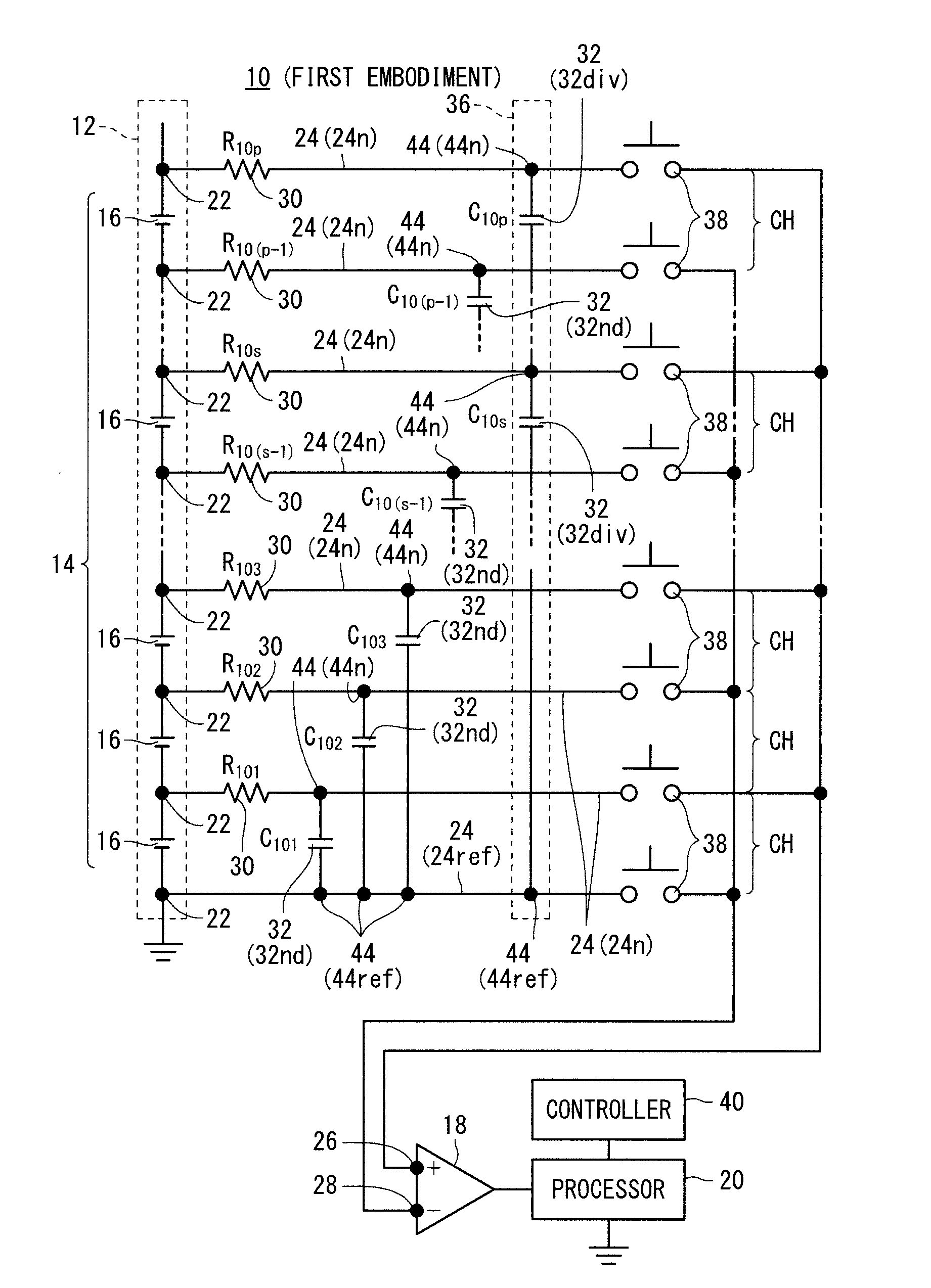
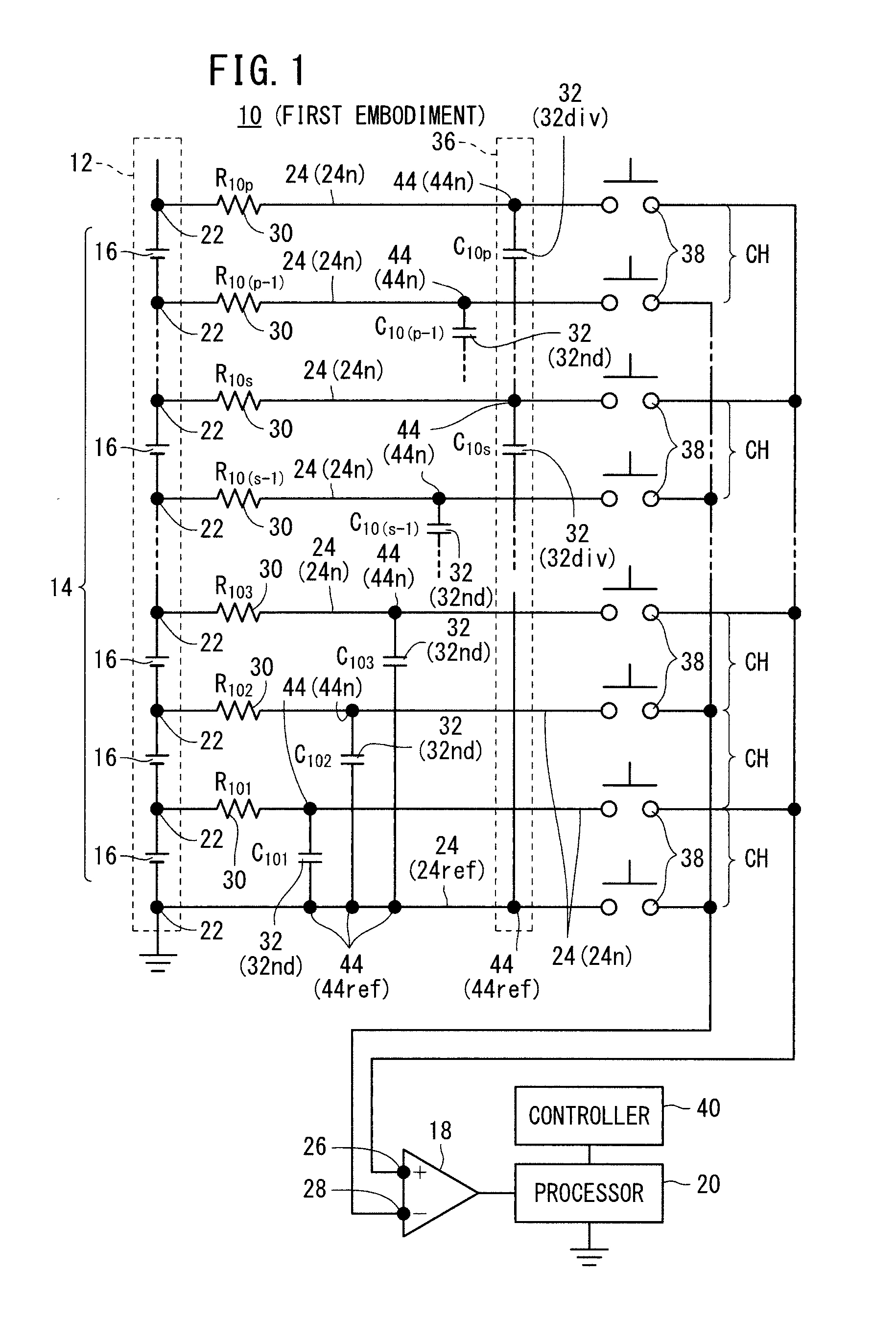
[0050]FIG. 1 is a circuit diagram showing an overall arrangement of a voltage measuring device 10 according to a first embodiment of the present invention. The voltage measuring device 10 has an arrangement in which two RC filters are combined. As shown in FIG. 1, the voltage measuring device 10 includes a battery assembly 12 having a module array 14 made up of a plurality of series-connected battery modules 16 (hereinafter referred to as “modules 16”), a voltage measuring circuit 18 to which voltages across the modules 16 (hereinafter referred to as “module voltages Vm”) are applied, and a processor 20 for detecting module voltages Vm based on an output signal from the voltage measuring circuit 18. The voltage measuring circuit 18 and the processor 20 jointly make up a voltage detecting means.

[0051]Each of the modules 16 comprises at least one cell. According to the first embodiment, each of ...

second embodiment

B. Second Embodiment

Arrangement in which Three RC Filters are Combined

B-1. Overall Arrangement

[0109]FIG. 12 is a circuit diagram showing a portion of a voltage measuring device 10A according to a second embodiment of the present invention. The voltage measuring device 10A according to the second embodiment is basically of the same arrangement as the voltage measuring device 10 according to the first embodiment, but differs therefrom in that, while the voltage measuring device 10 according to the first embodiment has two dividing capacitors 32div combined to provide two RC filters, the voltage measuring device 10A according to the second embodiment has three dividing capacitors 32div combined to provide three RC filters.

[0110]The voltage measuring device 10A includes the voltage measuring circuit 18, the processor 20, the switches 38, the controller 40, etc., similar to the case shown in FIG. 1, although such components are omitted from illustration in FIG. 12. In FIG. 12, the terms ...

third embodiment

C. Third Embodiment

Arrangement in which a Plurality of RC Filters are Combined

C-1. Overall Arrangement

[0153]FIG. 19 is a circuit diagram showing a portion of a voltage measuring device 10B according to a third embodiment of the present invention. The voltage measuring device 10B according to the third embodiment has an arrangement in which the number of RC filters is not limited, which is provided by generalizing, respectively, the voltage measuring device 10 according to the first embodiment and the voltage measuring device 10A according to the second embodiment.

[0154]More specifically, the voltage measuring device 10B measures a voltage across a battery assembly 12 (i.e., module voltages Vm across respective modules 16) comprising a module array 14 made up of p series-connected battery modules 16 (where p represents an integer of 3 or greater). Although not shown in FIG. 19, the voltage measuring device 10B also includes the voltage measuring circuit 18, the processor 20, the swit...


PUM


Abstract

Provided is a voltage measuring device capable of increasing the degree of freedom in the design of an RC filter (low-pass filter) while suppressing the withstand voltage limit of a capacitor. The voltage measuring device comprises: at least one divided capacitor group having a plurality of divided capacitors connected in series through measurement nodes and having one end connected to a reference node and the other end connected to a non-reference node; and at least one non-divided capacitor having one end connected to the reference node and the other end connected to a non-reference node to which the divided capacitors are not connected.

Description

TECHNICAL FIELD[0001]The present invention relates to a voltage measuring device for measuring a voltage across a battery assembly having a plurality of series-connected battery modules each of which is made up of at least one cell.BACKGROUND ART[0002]There have been developed voltage measuring devices for measuring a voltage across a battery assembly having a plurality of series-connected cells or battery modules. See, Japanese Laid-Open Patent Publication No. 2005-003618 (hereinafter referred to as “JP2005-003618A”), Japanese Laid-Open Patent Publication No. 2007-240299 (hereinafter referred to as “JP2007-240299A”), and U.S. Patent Application Publication No. 2008 / 0203976 (hereinafter referred to as “US2008 / 0203976A1”).[0003]The object of JP2005-003618A is to provide a power supply voltage measuring device for measuring accurate output voltages by correcting crosstalk (mutual voltage interference) between cells, which occurs in output voltages measured across respective cells due ...

Claims


Application Information

Patent Timeline
IPC IPC(8): G01R19/00G01R31/36H02J7/02
CPCG01R31/3627G01R19/0084G01R31/3835G01R31/396G01R31/385
Inventor OHNUKI, YASUMICHI
Owner HONDA MOTOR CO LTD
Why Eureka
Try Eureka