A linear actuator comprising an overload clutch

A technology for overload clutches and actuators, which is applied to mechanical equipment, belts/chains/gears, transmissions, etc., can solve problems such as speed limitations of actuators, and achieve the effect of facilitating installation work and improving self-breaking ability

Active Publication Date: 2007-02-28
LINAK AS
View PDF3 Cites 20 Cited by
  • Summary
  • Abstract
  • Description
  • Claims
  • Application Information

AI Technical Summary

Problems solved by technology

Moreover, due to the large torque load on the clutch, this position of the overload clutch also limits the speed of the actuator.

Method used


Image

  • A linear actuator comprising an overload clutch
  • A linear actuator comprising an overload clutch
  • A linear actuator comprising an overload clutch

Examples


Embodiment Construction

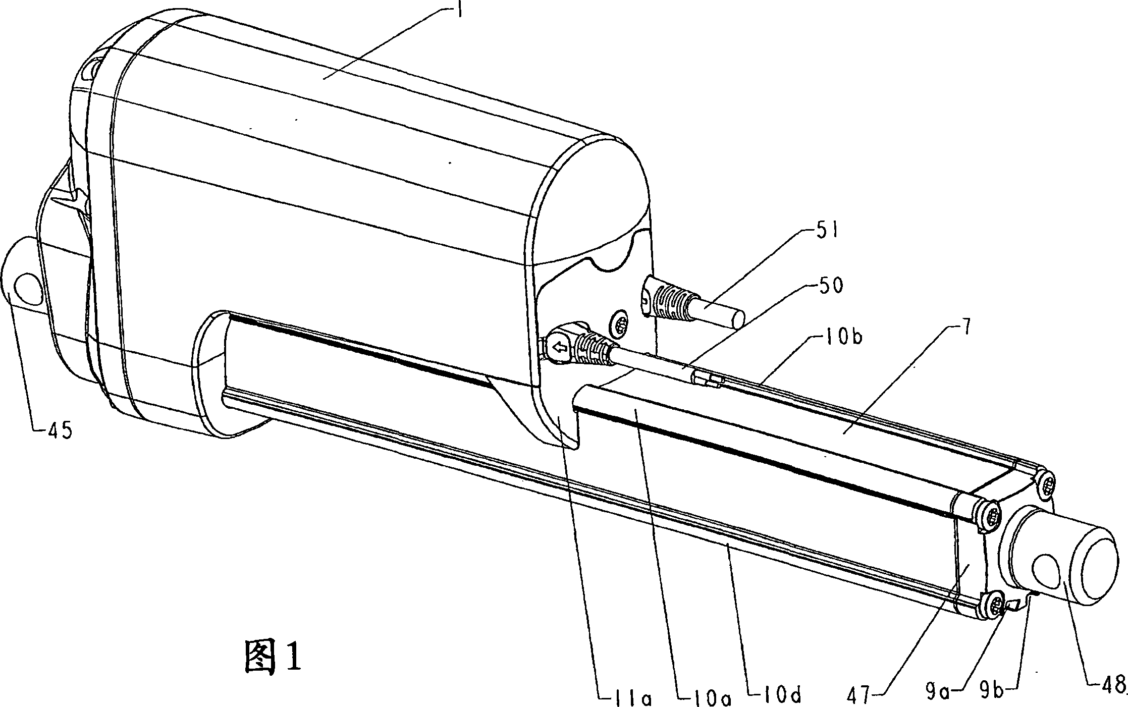
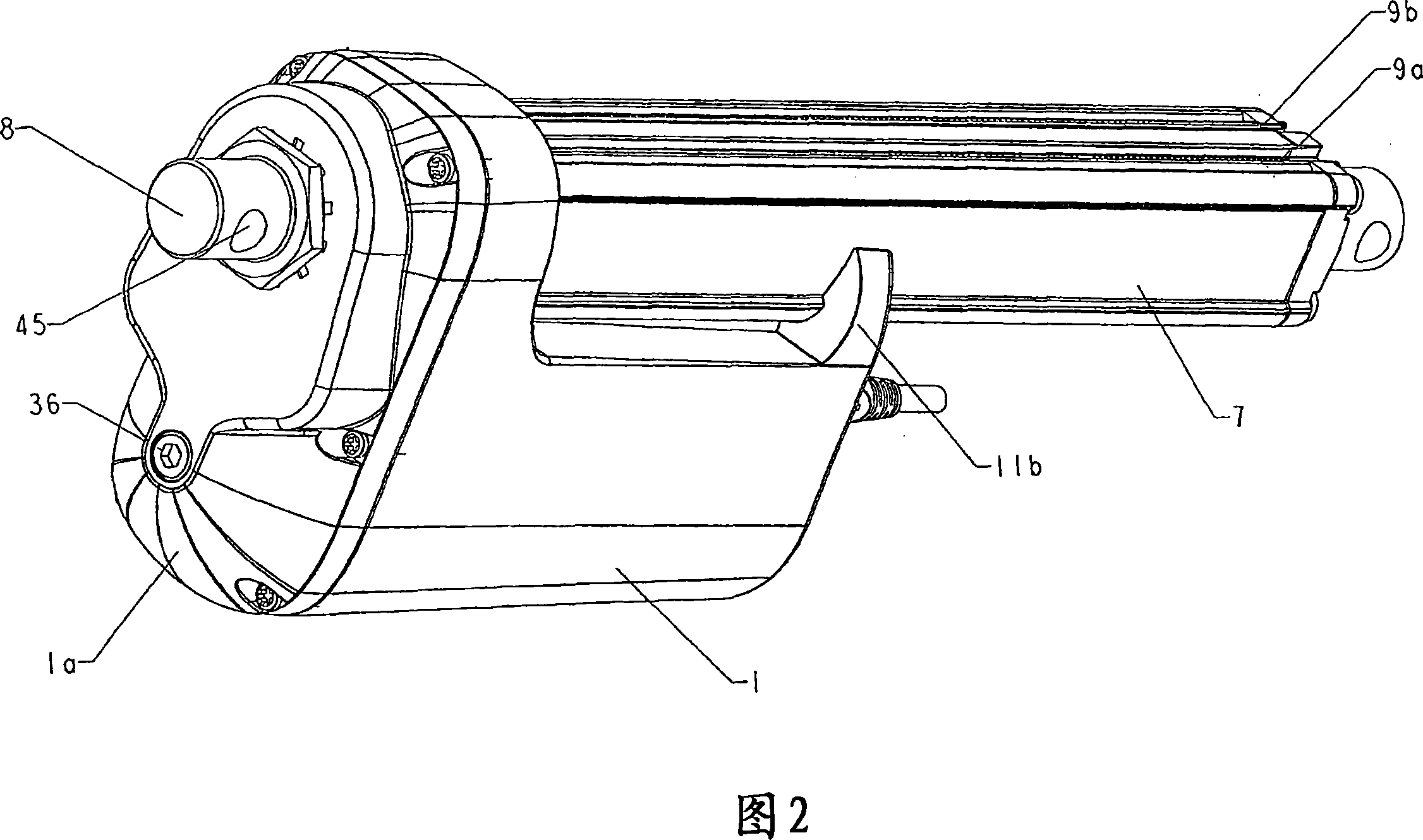
[0035] As shown in the accompanying drawing (Fig. 4), the main components of the actuator consist of a housing 1, a reversible motor 2, a multi-stage reduction gear 3, a main shaft 4, a main shaft nut 5, in the form of a tubular piston, also called an inner The actuating element 6 of the tube, the guide 7 , also called outer tube for this purpose, and finally the rear fastening 8 are formed.

[0036] The housing 1, made of molded aluminum for increased strength, has screw-fitted end shields 1a, and the joints are watertight (Figs. 1 and 2). The outer tube 7 is an extruded aluminum tube with a substantially square cross-section, assembled with screws, and its joints are also watertight. On one side thereof, the outer tube 7 is provided with two longitudinal grooves 9a, 9b, which can be used to mount additional equipment. In addition, the tube 7 is extruded with the helical channel of each corner, forming on the outside a longitudinally protruding strip 10a-d, the cross section...


PUM


Abstract

A linear actuator with a reversible electric motor (2) which drives a spindle (4) via a reduction gear with several stages and an activation element (6) connected with it. An overload clutch (21) is arranged in connection with the first stage or one of the first stages in the reduction gear. This is advantageous in terms of structure and load. Greater flexibility is achieved in the construction of the structure, and the clutch is moreover not loaded so severely.

Description

technical field [0001] The invention relates to a linear actuator as defined in the preamble of claim 1 . Background technique [0002] An actuator of the type described above for industrial purposes is sold by the American company Warner Electric Brake & Clutch Company under the trademark ELECTRAC. The actuator is provided with an overload clutch in the form of a ball and pawl clutch, which is arranged between the main shaft and the output side of the reduction gear. And because this position of the large moment load on the clutch overloads the clutch, the speed of the actuator is also limited. The actuator has been on the market in a fixed form for at least the last 30 years. Contents of the invention [0003] The object of the present invention is to provide an actuator of this type with improved performance and greater flexibility in constructing the structure. [0004] The actuator of the present invention is characterized in that the overload clutch is arranged to...

Claims


Application Information

Patent Timeline
Patent Type & Authority Applications(China)
IPC IPC(8): F16H25/20
CPCY10T74/18696Y10T74/18688Y10T74/18576F16H2025/2087F16H2025/2081F16H25/2021
Inventor B·克里斯滕森F·雅各布森K·克里斯蒂安森
Owner LINAK AS
Why Eureka
Try Eureka