Internal antenna for handset and design method thereof

A technology for built-in antennas and handheld devices, used in antennas, slot antennas, antenna components, etc., can solve the problems of difficult frequency characteristics stabilization, damage to the productivity of built-in antennas, and difficulties in the design and manufacture of built-in antennas, to achieve the effect of enhancing productivity.

Inactive Publication Date: 2007-02-28
E M W ANTENNA CO LTD
View PDF0 Cites 5 Cited by
  • Summary
  • Abstract
  • Description
  • Claims
  • Application Information

AI Technical Summary

Problems solved by technology

Internal antennas are more difficult to design and manufacture than traditional stick-out or external antennas
[0007] Specifically, because the antenna body is completely installed inside the main body of the handheld device, it is difficult to keep the frequency characteristics stable in assembly, and to maintain the frequency characteristics of the finished handheld device with the main body completely sealed
[0008] Therefore, there is a defect that the matching of the resonance frequency destroys the productivity of the built-in antenna

Method used


Image

  • Internal antenna for handset and design method thereof
  • Internal antenna for handset and design method thereof
  • Internal antenna for handset and design method thereof

Examples


Embodiment Construction

[0027] Preferred embodiments of the present invention will be described in detail below with reference to the accompanying drawings.

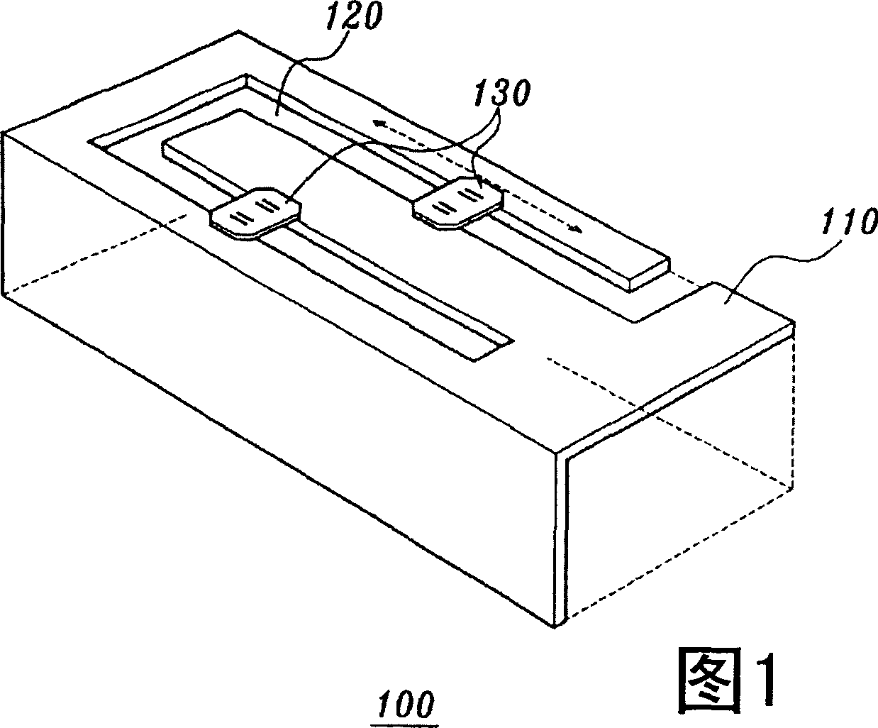
[0028] FIG. 1 illustrates a built-in antenna for a handheld device and a design method thereof according to one embodiment of the present invention.

[0029] As shown in FIG. 1 , the built-in antenna 100 includes a flat antenna body 110 having a predetermined bending line formed by a slit 120 .

[0030] Generally, the built-in antenna 100 uses the slit 120 to adjust the length and width of the bending line of the antenna body 110 to adjust the resonant frequency. For minor adjustments, inductive and / or capacitive elements (hereinafter referred to as L / C elements) 130 are connected along the gap 120 .

[0031] Specifically, the invented built-in antenna 100 includes an L / C element 130 to select the inductance value (L) and / or the capacitive value (C) to obtain the desired frequency characteristics.

[0032] In addition, the L / C element 130 ca...


PUM


Abstract

The present invention relates to an internal antenna for a handset and a design method thereof. The present invention provides an internal antenna for a handset and a design method thereof characterized in that a L / C element is attached to a slot line of an internal anetnna, the attached L / C element is moved along the slot line, or the L / C element having a predetermined inductance / capacitance is attached and detached, thereby easily matching a resonant frequency.

Description

technical field [0001] The present invention relates to built-in antennas for handheld devices, and more particularly, to built-in antennas for handheld devices and design methods thereof, wherein inductive and / or capacitive elements (hereinafter referred to as "L / C" elements) and built-in antennas The slot line is connected, or the connected L / C element is moved along the slot line, or an L / C element having a predetermined inductance / capacitance value is connected or disconnected, thereby easily matching the resonance frequency. Background technique [0002] In recent years, with the popularity of portable handheld devices such as portable phones, handheld digital assistants (PDAs) and wireless notebook computers, consumers' demands for terminals with different functions and designs are increasing. As a result, portable wireless terminals are not only being miniaturized, lightened and simplified gradually, but also the importance of design becomes more significant as their ...

Claims


Application Information

Patent Timeline
Patent Type & Authority Applications(China)
IPC IPC(8): H01Q1/24
CPCH01Q1/243H01Q5/321H01Q5/0034H01Q9/0442H01Q9/0421H01Q13/10B61H13/20B61D19/005B60T11/326E05F15/565B60Y2200/30E05Y2900/51
Inventor 柳秉勋成元模
Owner E M W ANTENNA CO LTD
Why Eureka
Try Eureka