Crane lower body optimised for transport

A crane and chassis technology, applied in the field of crane chassis, can solve the problems of high crane operation and use costs

Inactive Publication Date: 2007-03-07
TEREX GLOBAL GMBH
View PDF2 Cites 11 Cited by
  • Summary
  • Abstract
  • Description
  • Claims
  • Application Information

AI Technical Summary

Problems solved by technology

Therefore, the operation and use costs of this type of crane are relatively high

Method used


Image

  • Crane lower body optimised for transport
  • Crane lower body optimised for transport
  • Crane lower body optimised for transport

Examples


Embodiment Construction

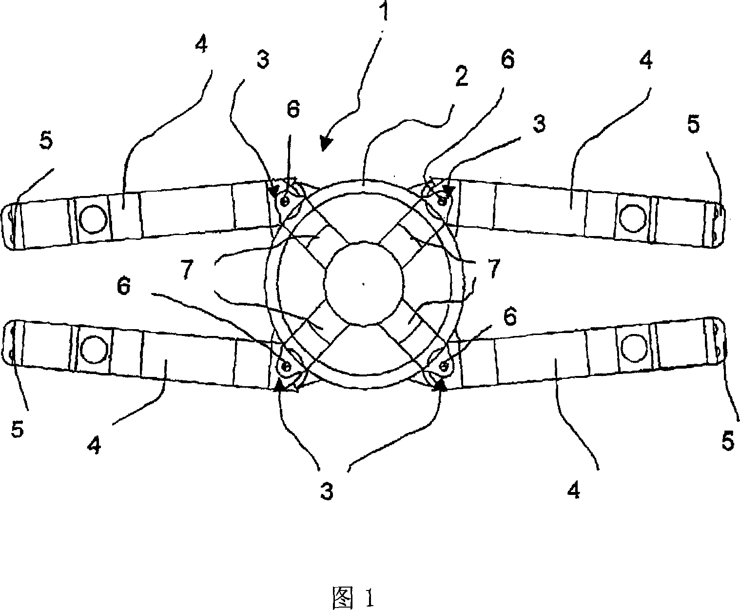
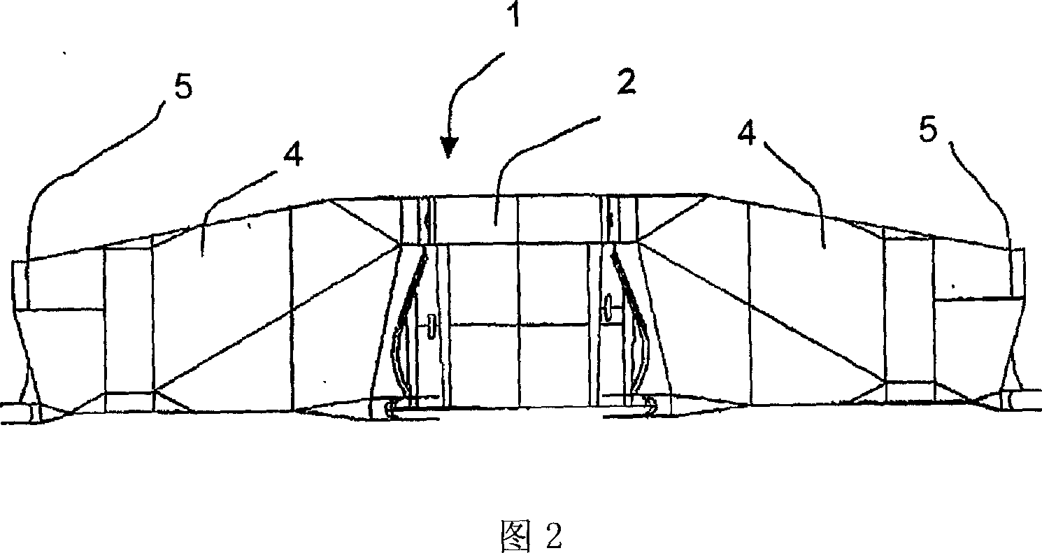
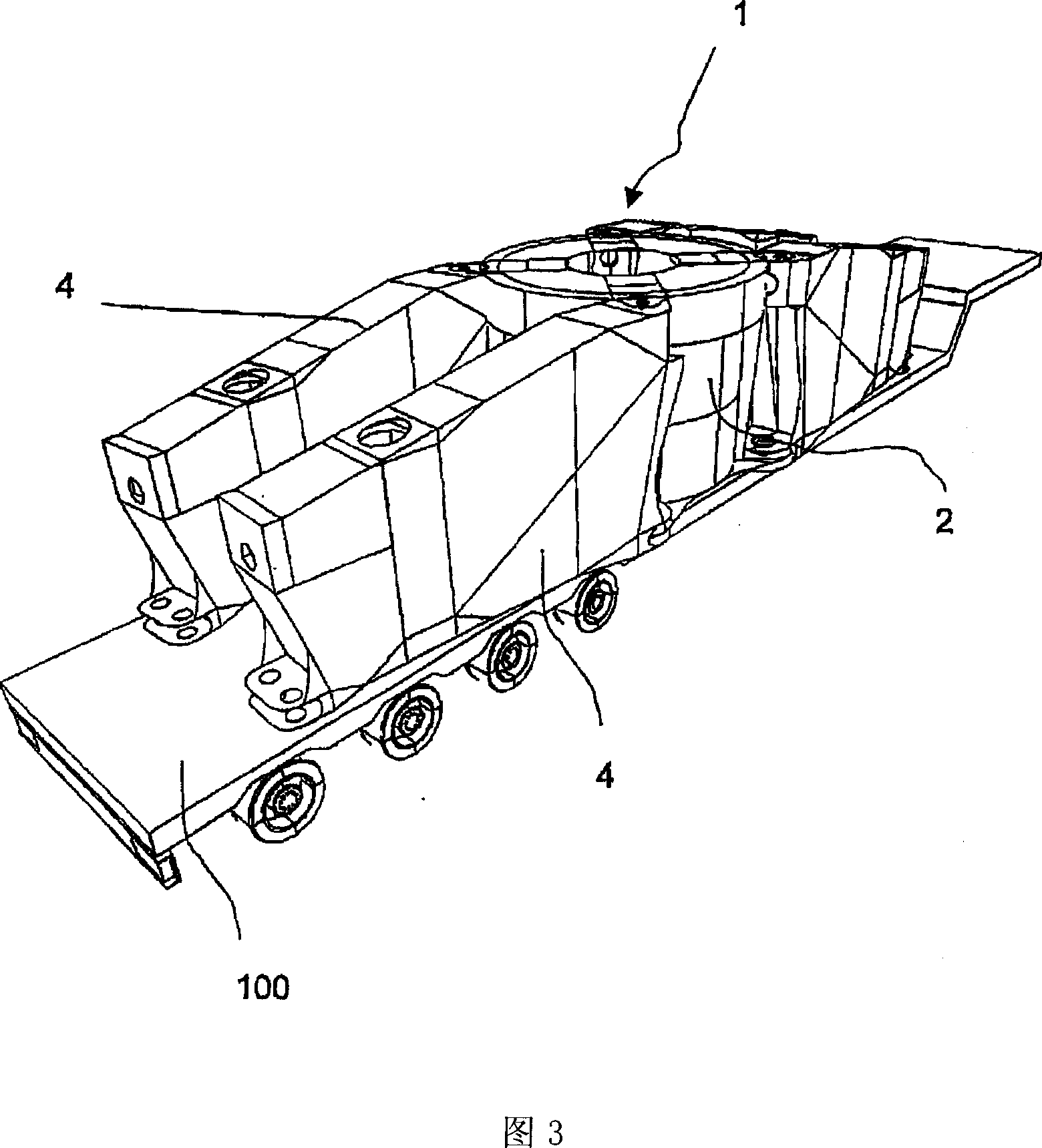
[0032] A first embodiment of the present invention will be described with reference to FIGS. 1-6. As shown in the top view of the crane chassis 1 of the present invention in FIG. 1 , the crane chassis of the present invention comprises a central portion forming a substantially pot-shaped base 2 . The pot-shaped base body 2 has a swivel bearing unit, which is only shown schematically here. A detachable crane superstructure 40 , only shown in FIG. 11 , which is rotatable on the tank-shaped base 2 , is mounted on the swivel support unit.

[0033] Four pivot hinges 3 are all formed on the outer circumference of the tank-shaped base 2 of the crane chassis 1 of the present invention; Outriggers 4. In the particular embodiment of the crane chassis 1 according to the invention shown here, the pivot joints 3 are arranged at a distance of 90° relative to the central axis of the base body 2 . It goes without saying that other angles can also be arranged between the pivot joints 3 . F...


PUM


Abstract

The invention concerns a crane undercarriage ( 1 ) that comprises a center section ( 2 ), which is constructed for removable mounting of a rotatable crane superstructure ( 40 ), and a plurality of outriggers ( 4 ), which are pivotably supported on the center section ( 2 ) for assuming a transport configuration and at least one operational configuration. The support elements ( 10; 20 ) necessary for the operation of the crane are attachable on the outriggers ( 4 ). In addition, the invention concerns a variable crane that comprises a crane undercarriage of the above-mentioned type and selectively a set of crawlers ( 10 ) or a set of floor jacks is removably mountable on the crane undercarriage ( 1 ).

Description

technical field [0001] The present invention relates to a transport-optimized crane chassis, in particular in a particular embodiment of the invention, optionally for a so-called CC-type crane or a PC-type crane. The first type of crane refers to a so-called crawler crane (CC for short), which is characterized by being able to move using crawlers. The second type of crane refers to a so-called pedestal crane (PC for short), wherein the crane chassis rests on a base support such as a floor. Background technique [0002] In general, operators are placing more and more demands on cranes that can lift large loads. The physical size of such cranes is therefore also increasing further. Especially lattice jib cranes increase in size even more. [0003] The supporting parts of this kind of crane, that is, the components that support the whole crane and put it on it, are different according to the environmental conditions of each construction site and the site, especially for this...

Claims


Application Information

Patent Timeline
Patent Type & Authority Applications(China)
IPC IPC(8): B66C23/62B66C23/78B66C23/36B62D55/084
CPCB66C23/80B62D55/062B66C23/62
Inventor 哈拉德·瑞丁格英戈·诺斯克
Owner TEREX GLOBAL GMBH
Why Eureka
Try Eureka