
Stress controlled lock in lock

A technology of stress and middle locking, which is applied in the direction of building locks, buildings, building structures, etc., can solve the problems of restraint lock safety technology, loss of lock control function, and affect the safety state of locking performance, so as to achieve the effect of multi-effect locking

Inactive Publication Date: 2007-03-07
TIANJIN HAIZHOU BRANCH TRADE & IND +1
View PDF0 Cites 9 Cited by
  • Summary
  • Abstract
  • Description
  • Claims
  • Application Information

AI Technical Summary

Problems solved by technology

However, due to the lack of the stress relationship of the mechanical check and balance principle in this traditional technical structure, once it is illegally damaged, the limited support force in the adhesion limit device is difficult to withstand the prying of external force, which will easily lead to the loss of the lock control function. thus affecting the safety state of the locking capability
Therefore, the existence of this problem has always been a difficult problem that restricts the improvement of lockset safety technology for a long time.

Method used


Image

  • Stress controlled lock in lock
  • Stress controlled lock in lock
  • Stress controlled lock in lock

Examples


Embodiment Construction

[0023] Other details and features of the present invention can be clearly understood by reading the embodiments described in detail below in conjunction with the accompanying drawings.

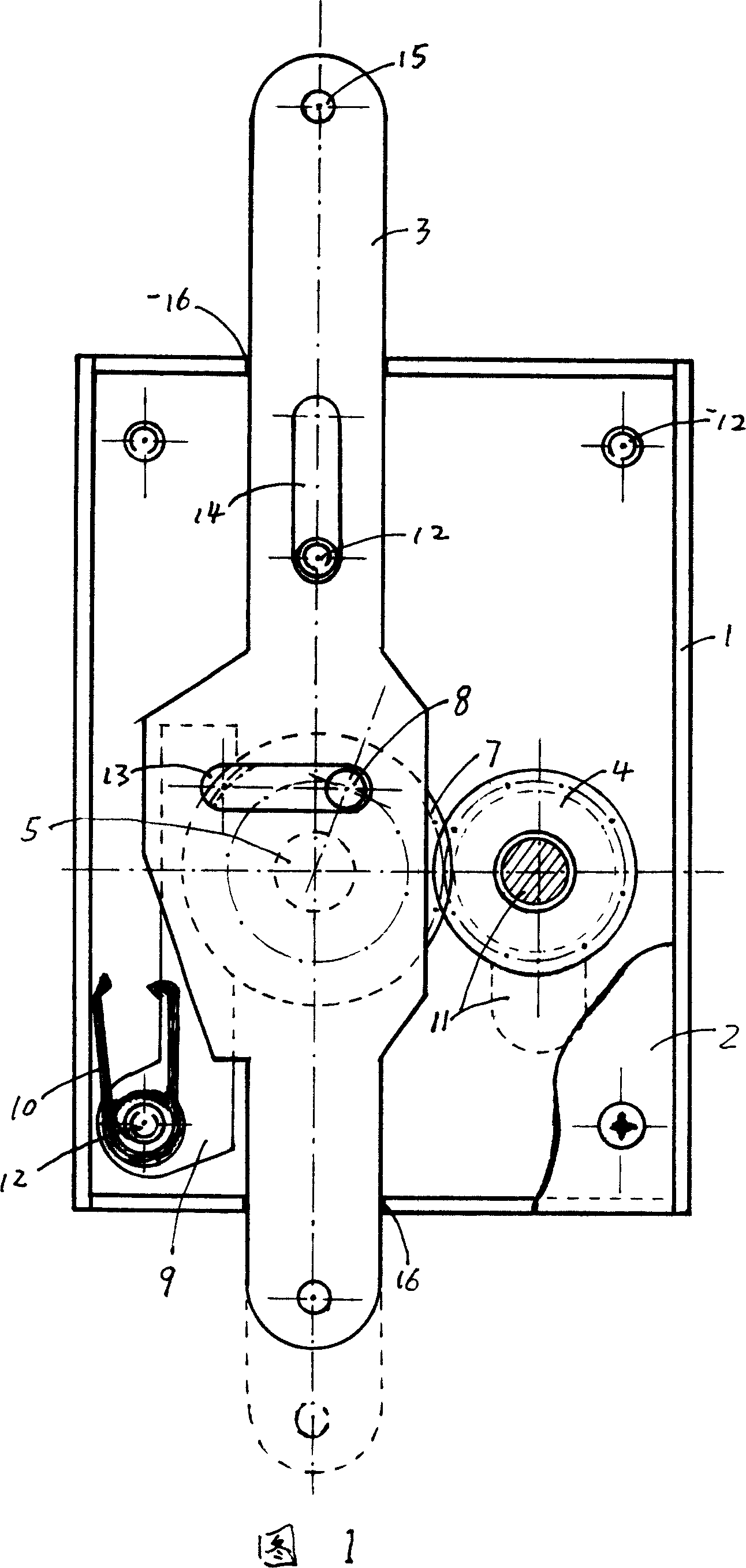
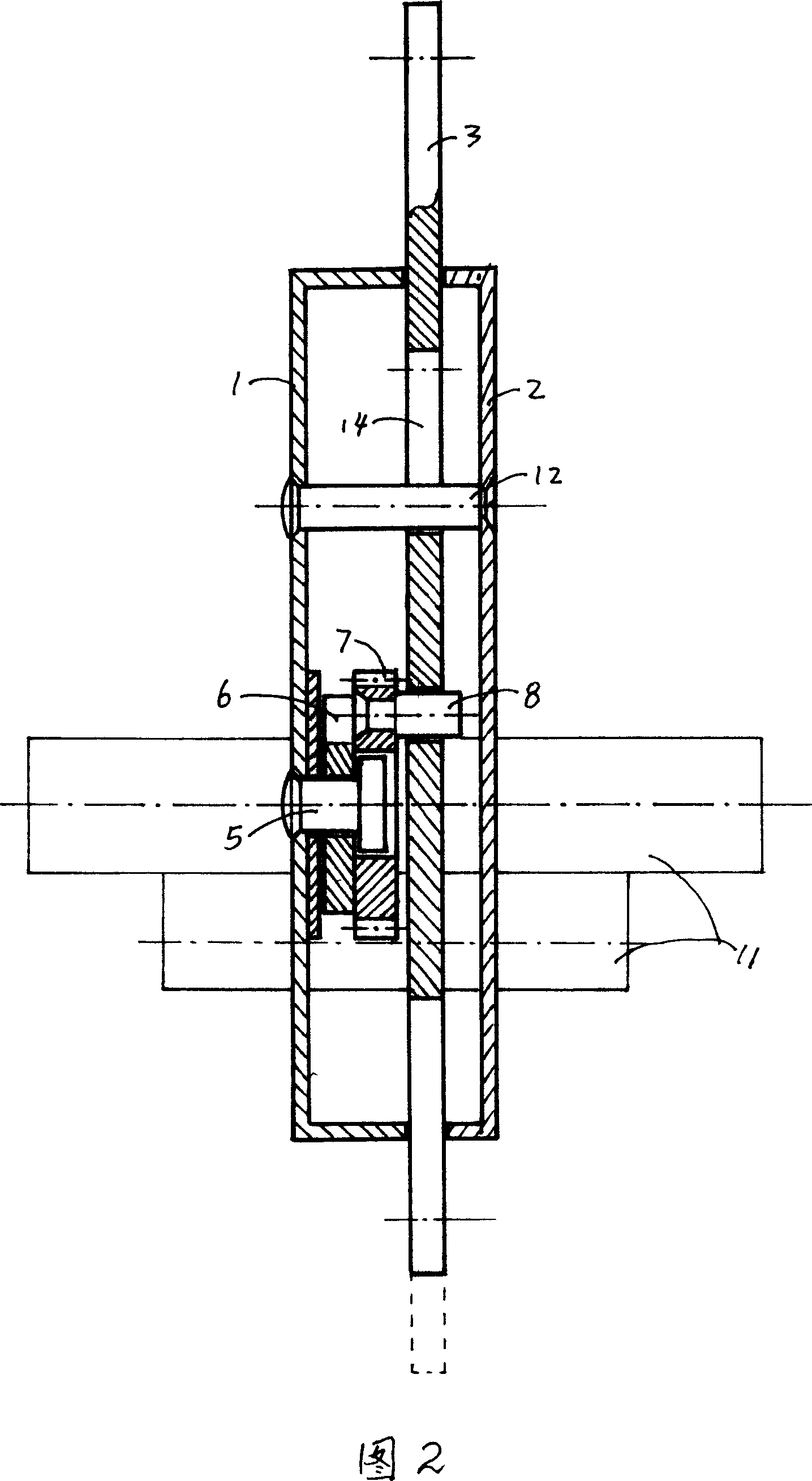
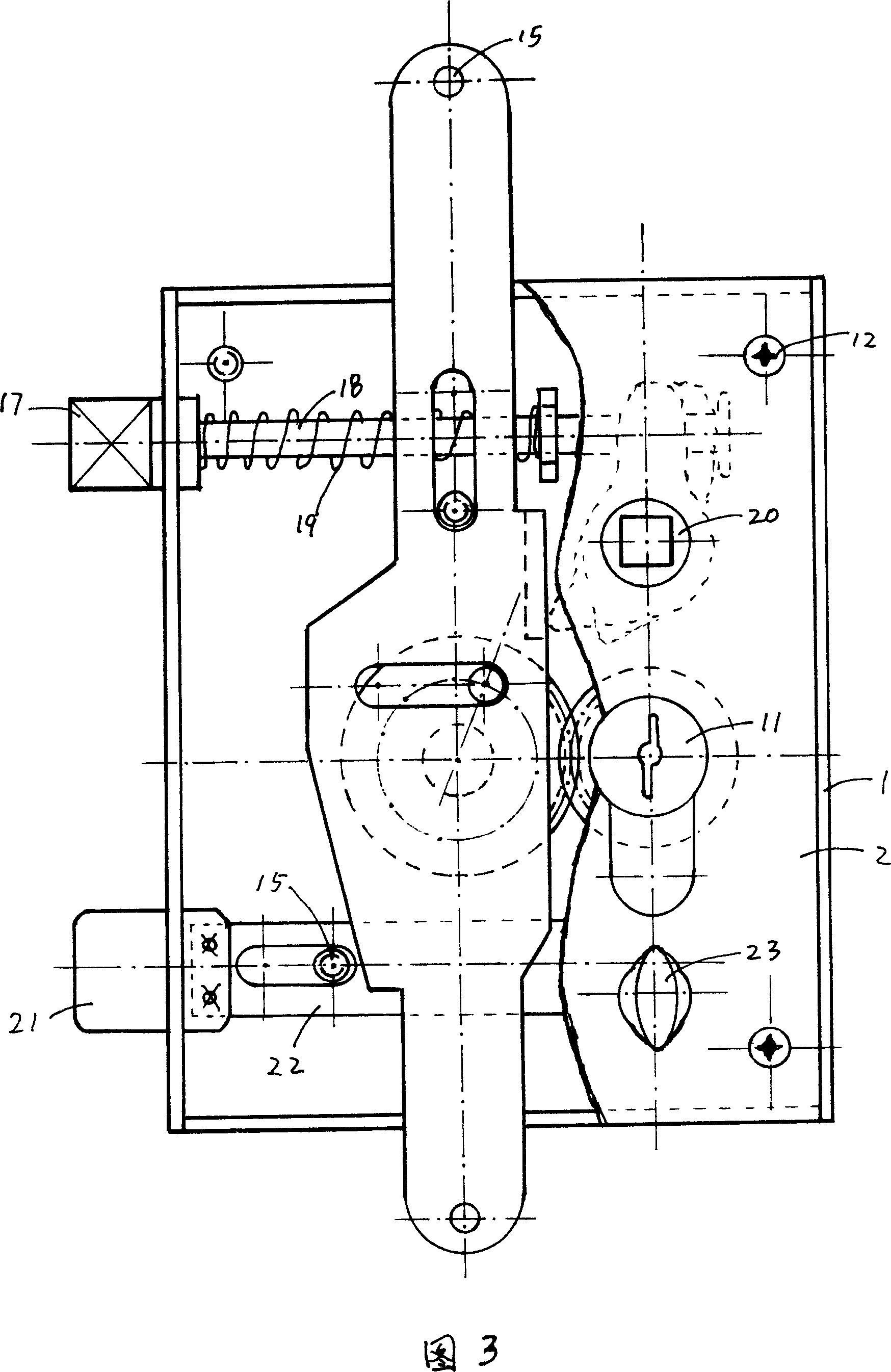
[0024] As shown in Figures 1-5, the stress control lock middle lock of the present invention consists of a lock body box 1 and a lid 2, a main control drive mechanism (as shown in Figures 1, 4, 11 in 2), and a stress actuator (as shown in Figure 1). 1, 6, 7, 8 in 2), half side shaft 5, locking stress shaft piece 3, reset induction (or safety mechanism) device (9, 10 in Fig. 1). It is characterized in that the lock body box 1 and the box cover 2 have a corresponding concentric special-shaped hole for the main control drive mechanism and a shaft pin fixing hole for the reset induction (or safety device) mechanism, and there is a half-type side shaft 5 fixed at the bottom of the lock body box 1 The force base hole of the lock body box 1 is provided with a groove 16 that can move up and down the l...


PUM


Abstract

This invention relates to stress balance relation lock, which comprises the following parts: lock case, case cover, main control drive structure, stress executive structure, semi-axis, locking stress axis, reset sensor device. The invention is characterized by the following: the stress executive structure an lock stress axis form mechanic stress relationship through main control drive structure main gear and passive gear; the bearing dial bolt lifts or contracts through stress axis, lock bolt; the passive stress gear axis line and lock stress axis vertical middle line are overlapped to generate lock dead angle at 15 degrees.

Description

technical field [0001] The invention relates to a stress compound locking control and locking safety device, in particular to a stress control locking middle lock generated by relying on the limiting force of a mechanical axis. Background technique [0002] At present, there are many types of lock products such as anti-theft door locks, safe locks, and car locks. However, in the technical design of these lock products, most of them add a set of "resistance limiting device" formed by springs (or extension springs) in addition to the main control lock effect function to achieve the satisfaction of the locking function. However, due to the lack of the stress relationship of the mechanical check and balance principle in this traditional technical structure, once it is illegally damaged, the limited support force in the adhesion limit device is difficult to withstand the prying of external force, which will easily lead to the loss of the lock control function. This affects the s...

Claims


Application Information

Patent Timeline
Patent Type & Authority Applications(China)
IPC IPC(8): E05B63/14
Inventor 朱玉国
Owner TIANJIN HAIZHOU BRANCH TRADE & IND
Learn More