
Virtual microscopic section method and system

A virtual slice and microscope technology, applied in microscopes, optics, instruments, etc., can solve the problems of large storage space, slow network transmission speed, popularization and application, etc., and achieve the effects of fast remote consultation, convenient exchange of diagnostic opinions, and reduced dependence

Inactive Publication Date: 2007-03-07
MOTIC CHINA GRP CO LTD
View PDF1 Cites 15 Cited by
  • Summary
  • Abstract
  • Description
  • Claims
  • Application Information

AI Technical Summary

Problems solved by technology

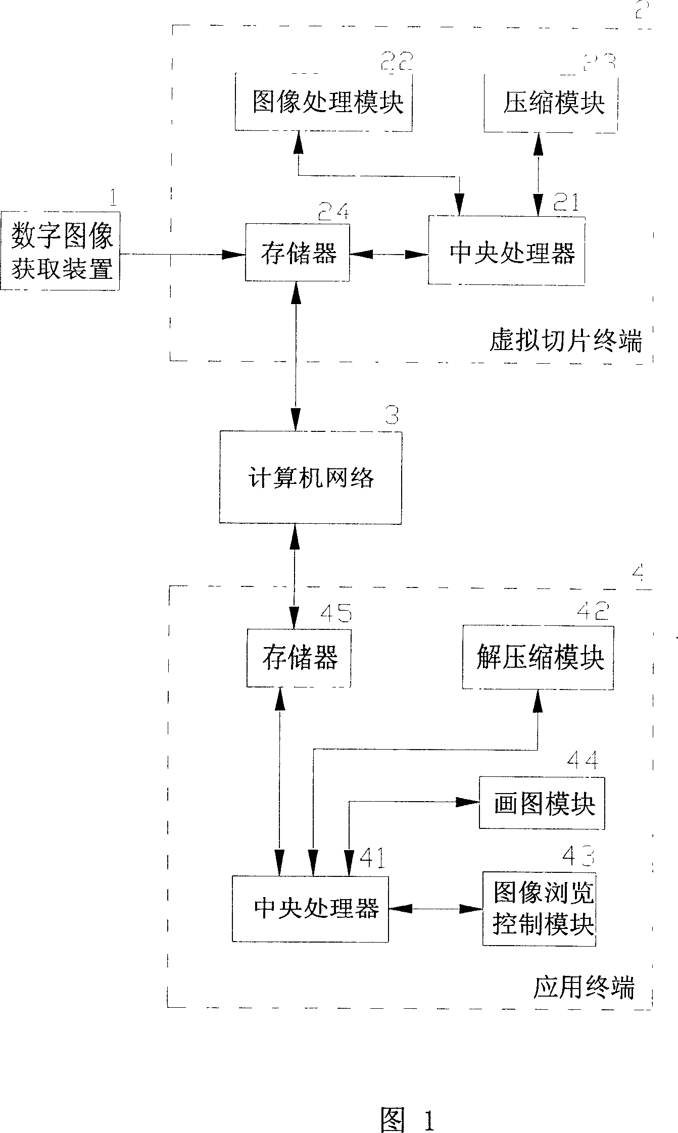
[0006] The present invention provides a virtual microscope slicing method and system, the main purpose of which is to overcome the problems in the prior art in the process of transmitting digitized images of pathological slices through computer networks due to the large electronic storage space and slow network transmission speed, etc. The problem of not being popularized and applied due to factors

Method used


Image

  • Virtual microscopic section method and system
  • Virtual microscopic section method and system
  • Virtual microscopic section method and system

Examples


specific Embodiment 2

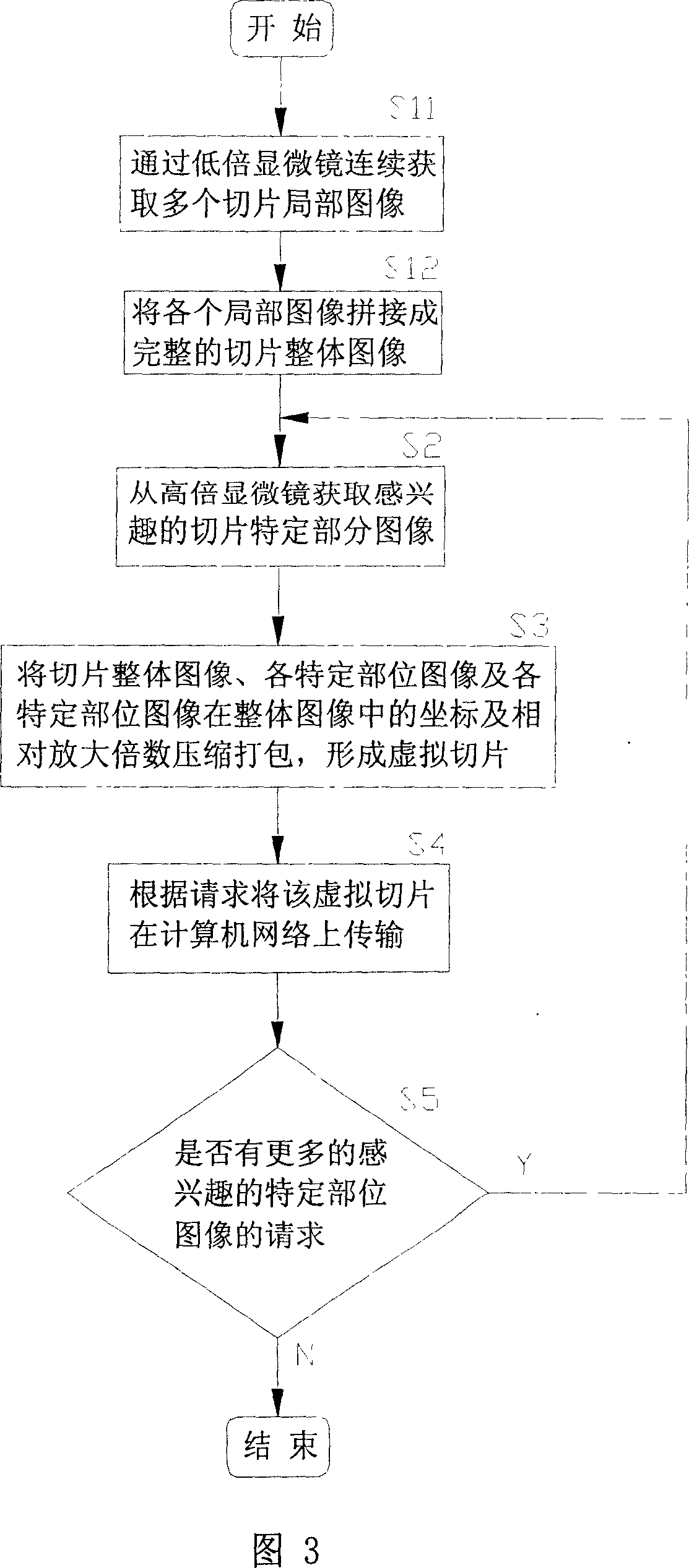
[0034] The second embodiment of the present invention is similar to the first embodiment in its basic structure and processing flow. The main difference is that the digital image acquisition device 1 in this embodiment includes a low-magnification microscope for acquiring continuous images of slices for splicing into an overall image of the slices, instead of a scanner or a digital camera. The processing flow of the virtual slicing terminal 2 is correspondingly different. Referring to FIG. 3, the main difference lies in the continuous acquisition of multiple slice partial images through a low-magnification microscope (step S01), and then splicing each partial image into a complete slice overall image (Step S02 ), the way of acquiring the overall image of the slice is different.

[0035] It should be noted that in the above description, for the convenience of explanation, the virtual slice terminal 2 and the application terminal 4 are described as two independent parts, which a...


PUM


Abstract

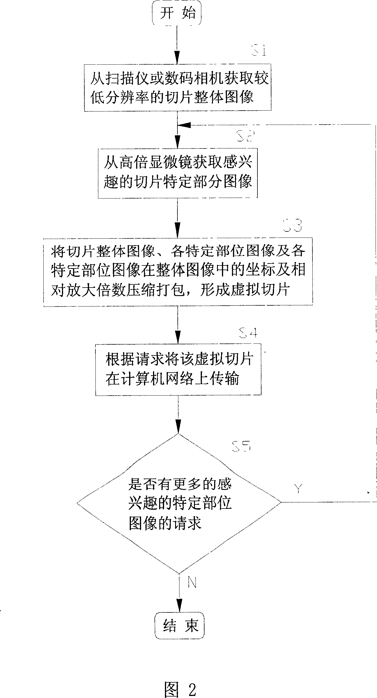
This invention relates to microscope slice method, which comprises the following steps: using total image with low resolution as virtual slice background image and establishing coordinates and background image on special part with high resolution with large times; then compressing it into virtual slice through network to user for decompressing virtual slice for displaying background image; then displaying image special part through coordinates. The virtual microscope slice system comprises the image catch device, virtual slice terminal, application terminal, virtual slice terminal.

Description

technical field [0001] The invention relates to a method and system for virtual microscope sectioning, in particular to a method and system for making, transmitting and displaying virtual microscope sections. Background technique [0002] Microscopes and tissue sections have been invented for more than 300 years and are widely used in clinical diagnosis, scientific research and teaching. With the advent of the computer and information age, people gradually try to digitize the magnified images of tissues collected by the microscope, and then transmit the information from one computer terminal to another computer terminal through the computer network, so as to carry out long-distance real-time or Lagging observation, thus overcoming the limitations of geography and time, greatly improving the efficiency, flexibility and accuracy of work and study. However, the existing analog slicing and remote microscope systems are far from meeting the needs of actual work and study because...

Claims


Application Information

Patent Timeline
IPC IPC(8): H04N1/41G02B21/00
Inventor 杨泽声
Owner MOTIC CHINA GRP CO LTD
Learn More