DC/DC converter conversion control system
A conversion control and converter technology, which is applied in the control/regulation system, output power conversion device, DC power input conversion to DC power output, etc., can solve the problems of not adapting to the integrated control environment, large volume, complex structure, etc. It achieves the effect of being conducive to integrated design, small system size and simple design structure
- Summary
- Abstract
- Description
- Claims
- Application Information
AI Technical Summary
Problems solved by technology
Method used
Image
Examples
Embodiment 1
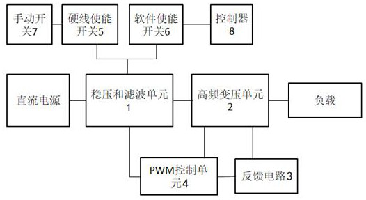
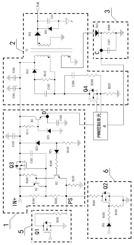
[0097] A DC / DC converter conversion control system, the control system includes: a voltage stabilizing and filtering unit 1, a high-frequency transforming unit 2, a feedback circuit 3, a PWM control unit 4, a hard-wire enable switch 5, and a software enable switch 6;
[0098] The voltage stabilizing and filtering unit 1 supplies power to the high-frequency transformer unit 2 and the PWM control unit 4, the output terminal of the high-frequency transformer unit 2 is connected to the load, and the feedback terminal of the high-frequency transformer unit 2 is connected to the feedback circuit 3, the output end of the feedback circuit 3 is connected to the feedback signal input end of the PWM control unit 4, and the control signal output end of the PWM control unit 4 is connected to the control end of the high-frequency transformer unit 2. connected, the PWM control unit 4 obtains the feedback signal of the high-frequency transformer unit 2, and controls the output voltage of the ...
Embodiment 2
[0119] Embodiment 2 is basically the same as Embodiment 1, and its difference is:
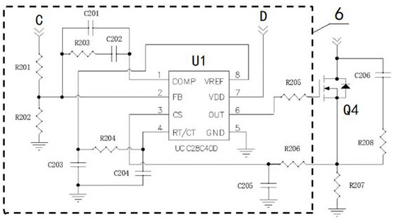
[0120] The PWM control unit 4 includes a control chip U1, a current limiting resistor R201, a sixth voltage dividing resistor R202, a compensation capacitor C201, a gain resistor R203, a gain capacitor C202, a seventh filter capacitor C203, a timing resistor R204, a timing capacitor C204, a first Fifth filter capacitor C205, second bias resistor R205, fifth resistor R206;
[0121] The FB pin of the control chip U1 is connected to one end of the sixth voltage dividing resistor R202 and one end of the current limiting resistor R201 at the same time, the other end of the sixth voltage dividing resistor R202 is grounded, and the other end of the current limiting resistor R201 One end is connected to the cathode of the fourth diode D13;
[0122] The FB pin of the control chip U1 is connected to one end of the compensation capacitor C201, the other end of the compensation capacitor C201 is connected...
Embodiment 3
[0128] Embodiment 3 is basically the same as Embodiment 2, and its difference is:
[0129] The manual switch 7 is a vehicle ON switch, and the controller 8 is a vehicle controller.
PUM
 Abstract
Description
Claims
Application Information
 - R&D
- Intellectual Property
- Life Sciences
- Materials
- Tech Scout
- Unparalleled Data Quality
- Higher Quality Content
- 60% Fewer Hallucinations
Browse by: Latest US Patents, China's latest patents, Technical Efficacy Thesaurus, Application Domain, Technology Topic, Popular Technical Reports.
© 2025 PatSnap. All rights reserved.Legal|Privacy policy|Modern Slavery Act Transparency Statement|Sitemap|About US| Contact US: help@patsnap.com


