A method, a system and a computer program for validation of geometrical matching in a medical environment

A computer program and geometry technology, applied in the field of computer programs, can solve the problems of inability to quantitatively estimate the geometry of anatomical positions and the spatial consistency of the geometry of implants

Inactive Publication Date: 2007-03-07
KONINKLIJKE PHILIPS ELECTRONICS NV
View PDF1 Cites 3 Cited by
  • Summary
  • Abstract
  • Description
  • Claims
  • Application Information

AI Technical Summary

Problems solved by technology

[0006] A disadvantage of the known method is the inability to quantitatively assess the spat

Method used


Image

  • A method, a system and a computer program for validation of geometrical matching in a medical environment
  • A method, a system and a computer program for validation of geometrical matching in a medical environment
  • A method, a system and a computer program for validation of geometrical matching in a medical environment

Examples


Embodiment Construction

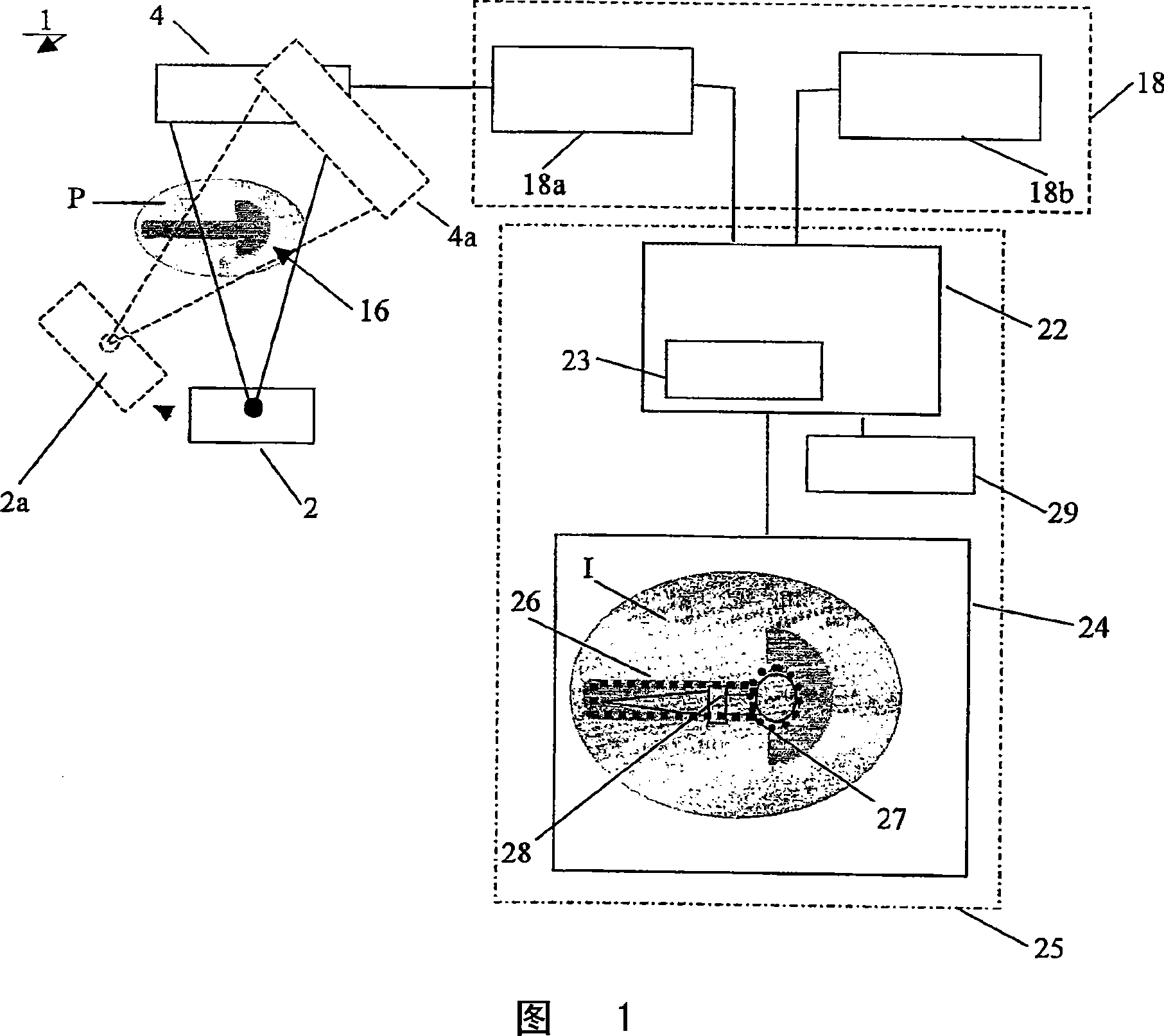
[0056] Figure 1 shows a schematic diagram of one embodiment of the system according to the invention. According to the invention, the system 1 to allow confirmation of a match between the geometry of an anatomical location and the geometry of an object envisaged to be placed in said anatomical location operates using individual data sets representing anatomical locations and objects.

[0057] A first data set 18 a representing an anatomical location is obtained by means of suitable imaging using the medical diagnostic device 2 . FIG. 1 shows in a simplified manner an embodiment of an X-ray unit adapted to obtain a data set 18a representative of an anatomical position of a patient P. As shown in FIG. In this embodiment, joint 16 is shown as an anatomical location. In order to achieve a spatial match between the anatomical location 16 and an object, eg a joint implant, which is supposed to be placed in said location, at least two projections of the anatomical location 16 are ch...


PUM


Abstract

A method, a system and a computer program for geometrical matching between an anatomical site and an object. A first data set (18a), representative of the anatomical site, is obtained by means of a suitable imaging using a medical diagnostic apparatus (2). The second data set (18b) comprises a geometric description of the object or its image obtained by means of a medical diagnostic unit. The system (1) comprises processing means (22) to retrieve the first data set (18a) and the second data set (18b) in order to produce a superimposed image (I) comprising the image (26) based on the first data set (18a) and an image (28), based on the second data set (18b). Images (26) and (28) are visualized on a display (24) using the same magnification factor and substantially the same orientation in space. The system (1) comprises automatic delineation means (23), and image manipulation means.

Description

technical field [0001] The present invention relates to a method of confirming a match between the geometry of an anatomical location and the geometry of an object envisioned to be placed at said anatomical location. [0002] The invention also relates to a system allowing to confirm the match between the geometry of an anatomical location and the geometry of an object envisioned to be placed at said anatomical location. [0003] The invention also relates to a computer program. Background technique [0004] An embodiment of the method proposed in the opening paragraph is known from US 6,424,332. Said known method is suitable for comparing a digitized image of an implanted joint with a medical image representing the geometry of the joint in the human body, said medical image being provided on a hard copy carrier. Known hard copy carriers consist of x-ray slide films mountable on the front of a suitable display device, onto which a digitized image of the implant is projecte...

Claims


Application Information

Patent Timeline
IPC IPC(8): A61B19/00A61B6/00G06T5/00G06T7/00
CPCG06T2200/04A61B19/52A61B19/50A61B2019/5289A61B6/583G06T2207/30052G06T19/00G06T2207/10072G06T7/0028G06T2210/41A61B34/10A61B90/36A61B2090/364G06T7/33
Inventor J·T·M·范维茨克
Owner KONINKLIJKE PHILIPS ELECTRONICS NV
Why Eureka
Try Eureka