Transmitter and receiver optical sub-assemblies with optical limiting elements

A technology of light-emitting components and light-receiving components, applied in the field of optical transceivers, can solve problems such as difficulty in eye safety control

Inactive Publication Date: 2007-03-07
FINISAR
View PDF0 Cites 25 Cited by
  • Summary
  • Abstract
  • Description
  • Claims
  • Application Information

AI Technical Summary

Problems solved by technology

Desiring to have a high maximum output power range for manufacturing yields tends to make eye safety control more difficult

Method used


Image

  • Transmitter and receiver optical sub-assemblies with optical limiting elements
  • Transmitter and receiver optical sub-assemblies with optical limiting elements
  • Transmitter and receiver optical sub-assemblies with optical limiting elements

Examples


Embodiment Construction

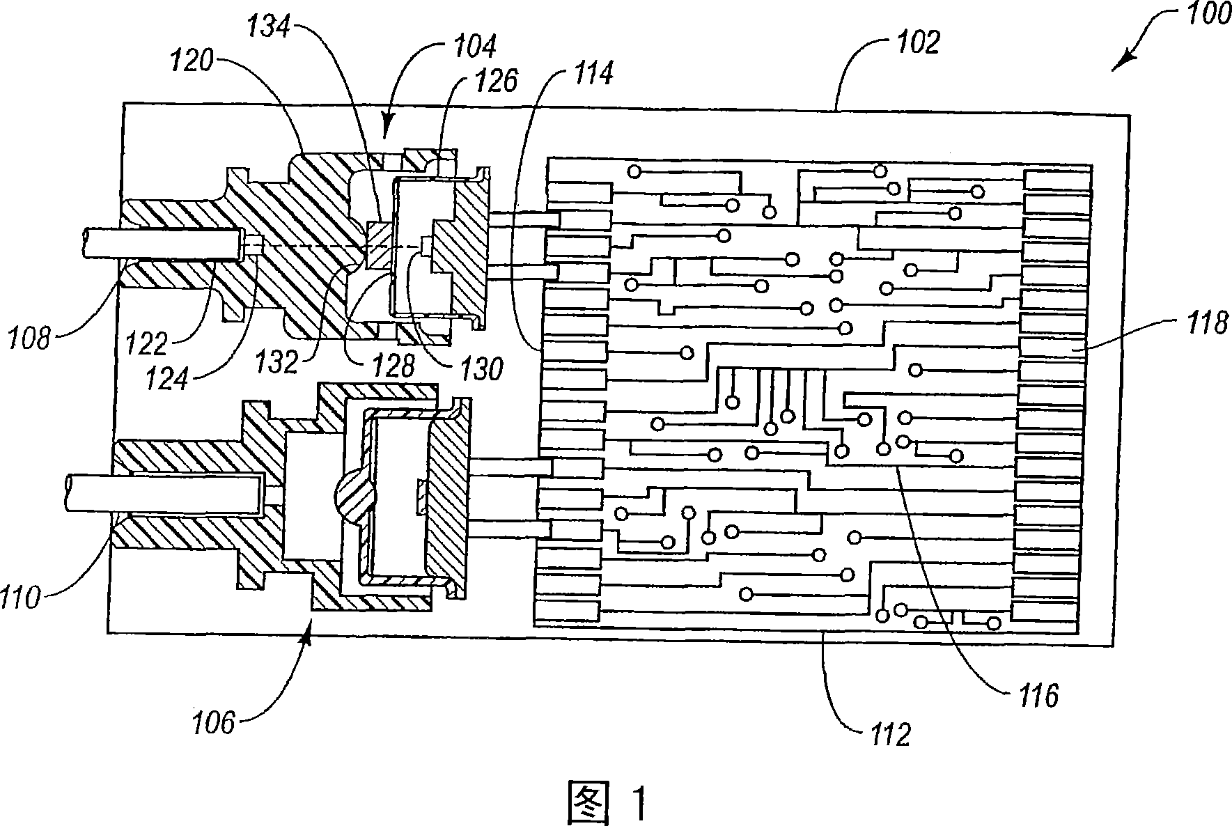
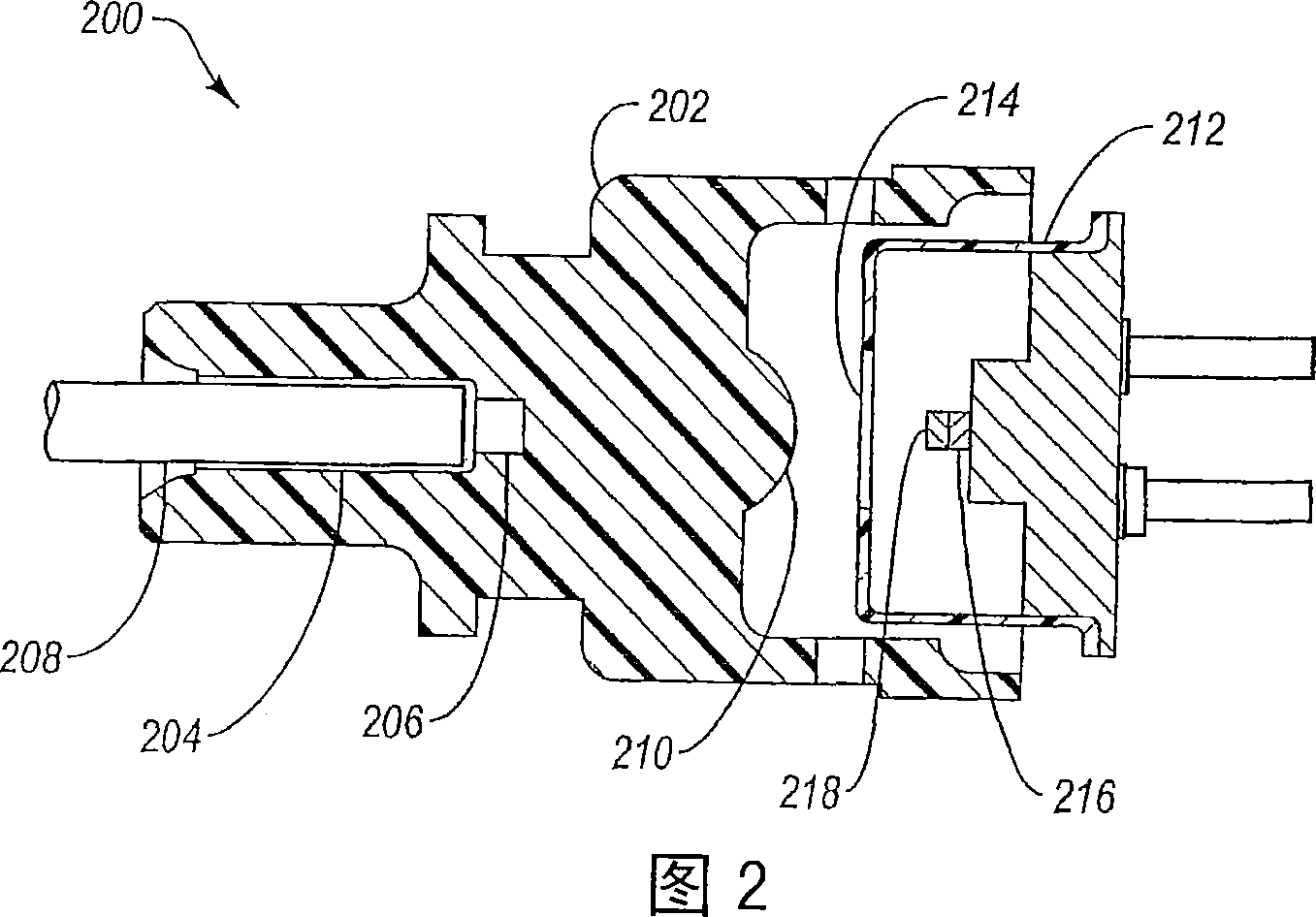
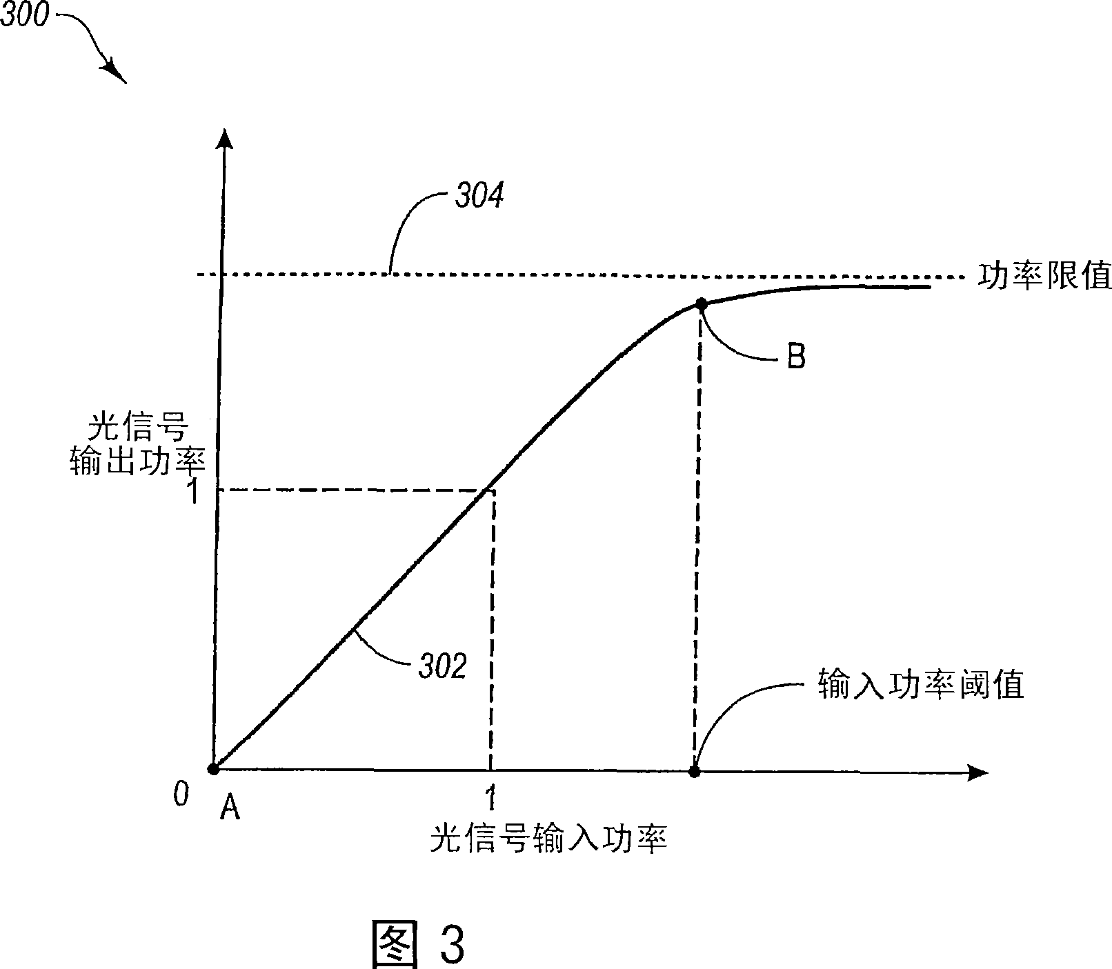
[0021] Exemplary embodiments of the present invention relate to optical transceivers that meet the relevant Eye safety requirements. The optical limiting element made of optical limiting material is used to optically attenuate the optical signal when the power level of the optical signal exceeds a predetermined threshold.

[0022] In an exemplary TOSA, a signal is transmitted from an optical transmitter, and the signal travels to a fiber container where the optical signal is received by an optical fiber. In order to ensure that the power of the optical signal received from the optical transmitter in the optical fiber does not exceed predetermined limits, such as eye safety limits, embodiments of the present invention include one or more between the optical limiting elements. Optical limiting elements effectively limit the power of transmitted optical signals by attenuating optical signals whose power levels exceed a desired threshold. By limiting the power of the optical si...


PUM


Abstract

A transmitter optical subassembly (104) includes an optical emitter (130) and a fiber receptacle (122) within which an optical fiber (108) is received. An optical limiting element (134) is positioned between the optical emitter (103) and the fiber receptacle (122). When an optical signal is emitted from the optical emitter, the optical signal passes through the optical limiting (134) element before the optical signal reaches the fiber receptacle (122) and is received the optical fiber. The optical limiting element (134) has a property such that if the power of the optical signal entering the optical limiting element (134) exceeds a predetermined limit, the power of the optical signal is optically attenuated so that the power of the optical signal exiting the optical limiting element remains below a predetermined limit.

Description

technical field [0001] The present invention relates generally to the field of optical transceivers. More specifically, embodiments of the present invention relate to eye safety requirements for optical signals transmitted from optical transceivers. Background technique [0002] Laser signals are used in a wide variety of different technologies and applications. For example, lasers have been widely used in the military range as range finders, as target designators, and in guidance systems. Lasers are also widely incorporated into communication systems for high speed data transfer. The actual use of lasers and the physical properties of different lasers vary widely. Some lasers emit low power signals, while others emit very high power signals. In many cases, light-sensitive devices, as well as the human eye, can be severely damaged by exposure to high-power laser signals. [0003] To protect the human eye from damaging laser signals, eye safety requirements have been dev...

Claims


Application Information

Patent Timeline
Patent Type & Authority Applications(China)
IPC IPC(8): H01S3/08H01S3/10H01S5/00H01S5/022
CPCG02B2006/4297H01S5/02212G02B6/4206H01S5/005H01S5/02284H01S5/02251
Inventor 刘易斯·B.·阿伦森
Owner FINISAR
Why Eureka
Try Eureka