Graphics processing apparatus and method for performing shading operations therein

A graphics processing and shader technology, applied in image data processing, processor architecture/configuration, 3D image processing, etc., can solve problems such as pipeline inefficiency, delay and bottleneck, and affect pipeline performance

Active Publication Date: 2007-03-14
VIA TECH INC
View PDF6 Cites 23 Cited by
  • Summary
  • Abstract
  • Description
  • Claims
  • Application Information

AI Technical Summary

Problems solved by technology

The complexity and size of graphics data in the pipeline implies pipeline inefficiencies, latencies, and bottlenecks that can significantly affect pipeline performance

Method used


Image

  • Graphics processing apparatus and method for performing shading operations therein
  • Graphics processing apparatus and method for performing shading operations therein
  • Graphics processing apparatus and method for performing shading operations therein

Examples


Embodiment Construction

[0035] Embodiments will be listed below, and detailed descriptions will be given in conjunction with the accompanying drawings. The description of the embodiments related to the illustrations is not intended to limit the present invention to the embodiments or the disclosed embodiments. On the contrary, it is intended to cover all alternatives, modifications, and equivalent designs.

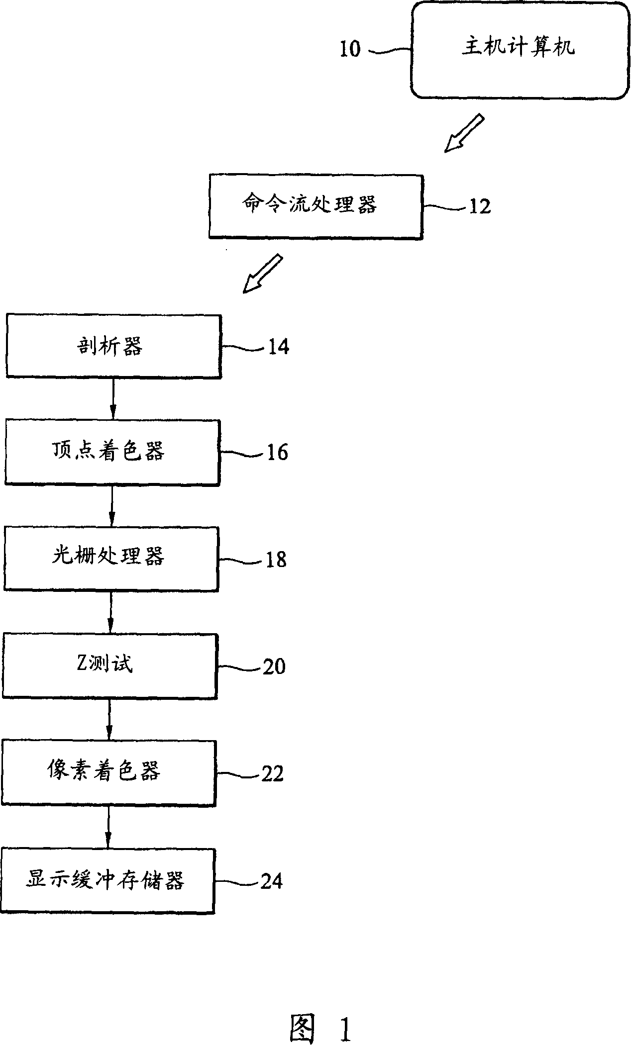
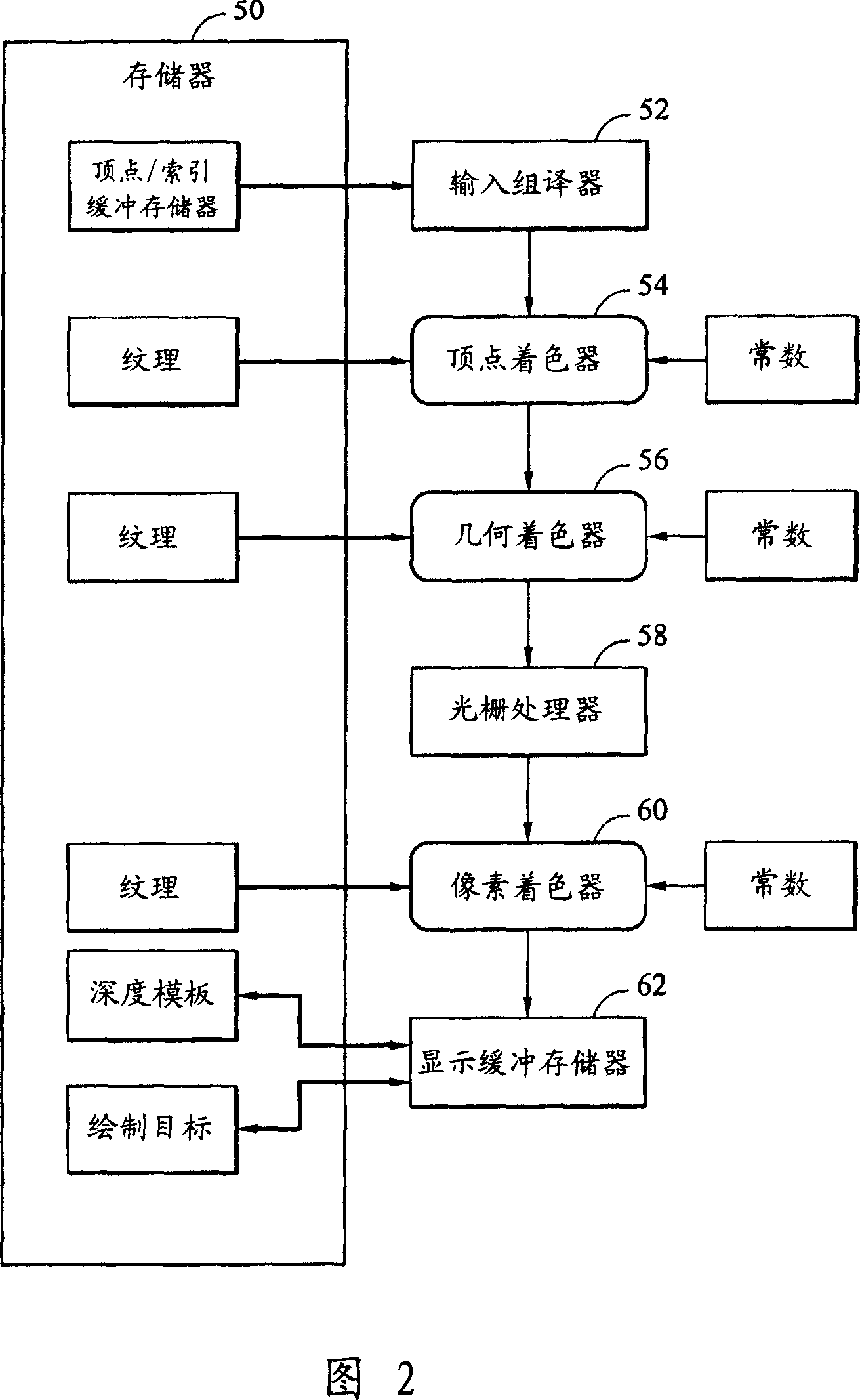
[0036] Referring now to FIG. 2, there is shown a block diagram of some components of an embodiment of the present invention. Figure 2 specifically shows the main components, including a pipelined graphics processor, configured to execute or implement an embodiment of the present invention. The first element is designated as an input assembler 52, which basically receives or reads vertices from memory, which vertices are used to form geometry and generate work items for the pipeline. In this regard, the input assembler 52 reads data from memory and generates triangles, lines, points, or other pi...


PUM


Abstract

The present disclosure is directed to novel methods and apparatus for managing or performing the dynamic allocation or reallocation of processing resources among a vertex shader, a geometry shader, and pixel shader of a graphics processing unit. In one embodiment a method for graphics processing comprises assigning at least one execution unit to each of a plurality of shader units, the plurality of shader units comprising a vertex shader, a geometry shader, and a pixel shader, wherein an execution unit assigned to a given shader unit performs processing tasks for only that shader unit, determining that one of the plurality of shader units is bottlenecked, and reassigning at least one execution unit from a non-bottlenecked shader unit to the shader unit determined to be bottlenecked.

Description

technical field [0001] The present invention relates to a computer graphics system, and more particularly to a system and method for managing calculations of graphics rendering operations. Background technique [0002] As is well known, three-dimensional ("3-D") computer graphics techniques are concerned with the generation or rendering of two-dimensional ("2-D") images of 3-D objects for display or presentation on a display device or screen, Examples include a cathode ray tube (CRT) or a liquid crystal display (LCD). The object can be simple geometric pixels such as a point, line segment, triangle or polygon. More complex objects can be drawn on the display device by a series of connected planar polygons, for example, by a series of connected planar triangles to represent the object. All geometric pixels can ultimately be described in terms of a vertex or set of vertices, such as coordinates (X, Y, Z) defining a point, such as the end point of a line segment, or a corner ...

Claims


Application Information

Patent Timeline
Patent Type & Authority Applications(China)
IPC IPC(8): G06T1/20G06T15/00
Inventor 焦阳苏奕荣
Owner VIA TECH INC
Why Eureka
Try Eureka