Electrical connection box

A technology of electrical connection boxes and connectors, applied in the direction of connection, multiple connection components, circuits, etc., can solve problems such as immersion

Active Publication Date: 2007-03-14
AUTONETWORKS TECH LTD +2
View PDF2 Cites 16 Cited by
  • Summary
  • Abstract
  • Description
  • Claims
  • Application Information

AI Technical Summary

Problems solved by technology

[0005] In the above-mentioned electrical connection box, water may pass through the gap betwee

Method used


Image

  • Electrical connection box
  • Electrical connection box
  • Electrical connection box

Examples


Embodiment Construction

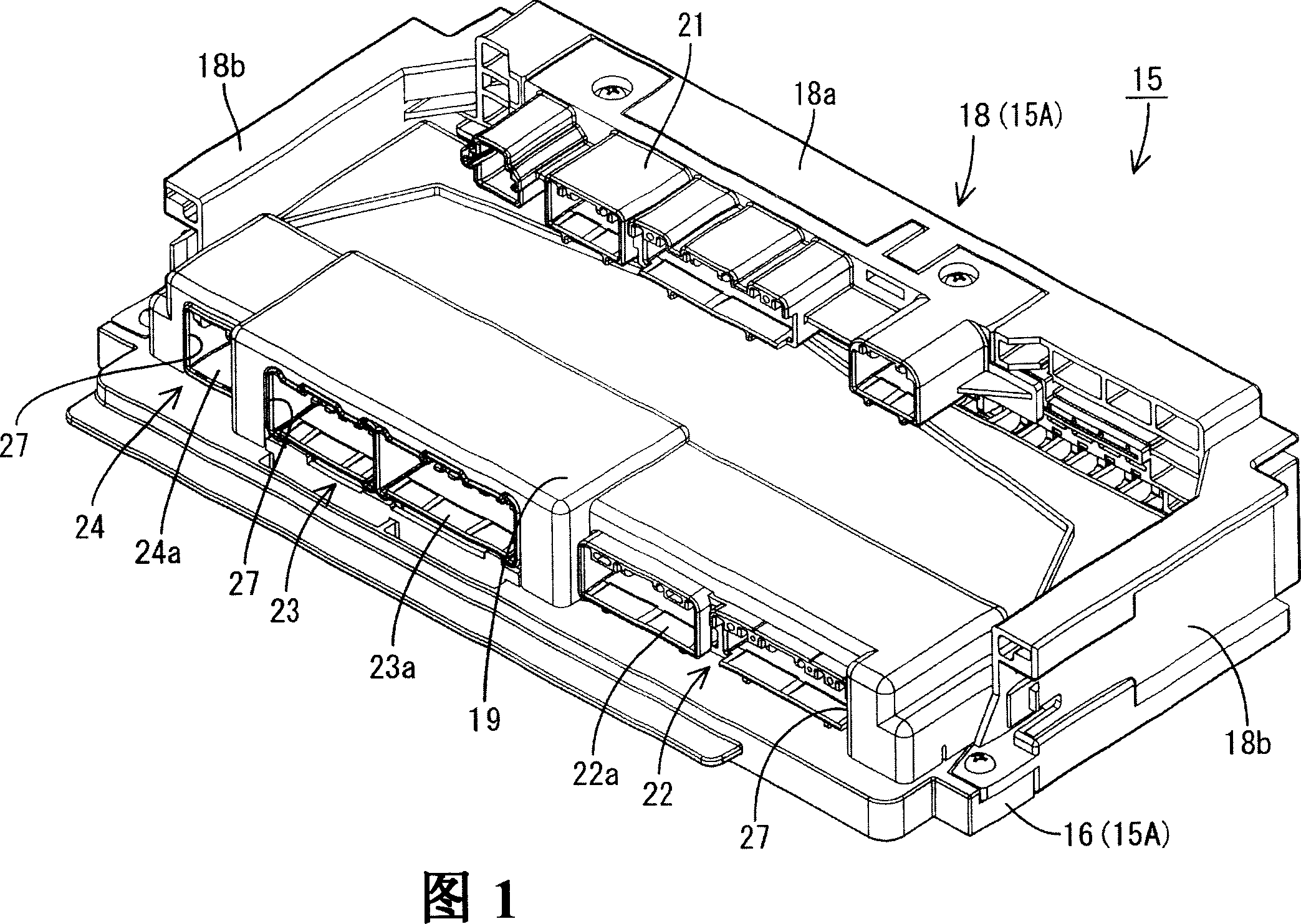
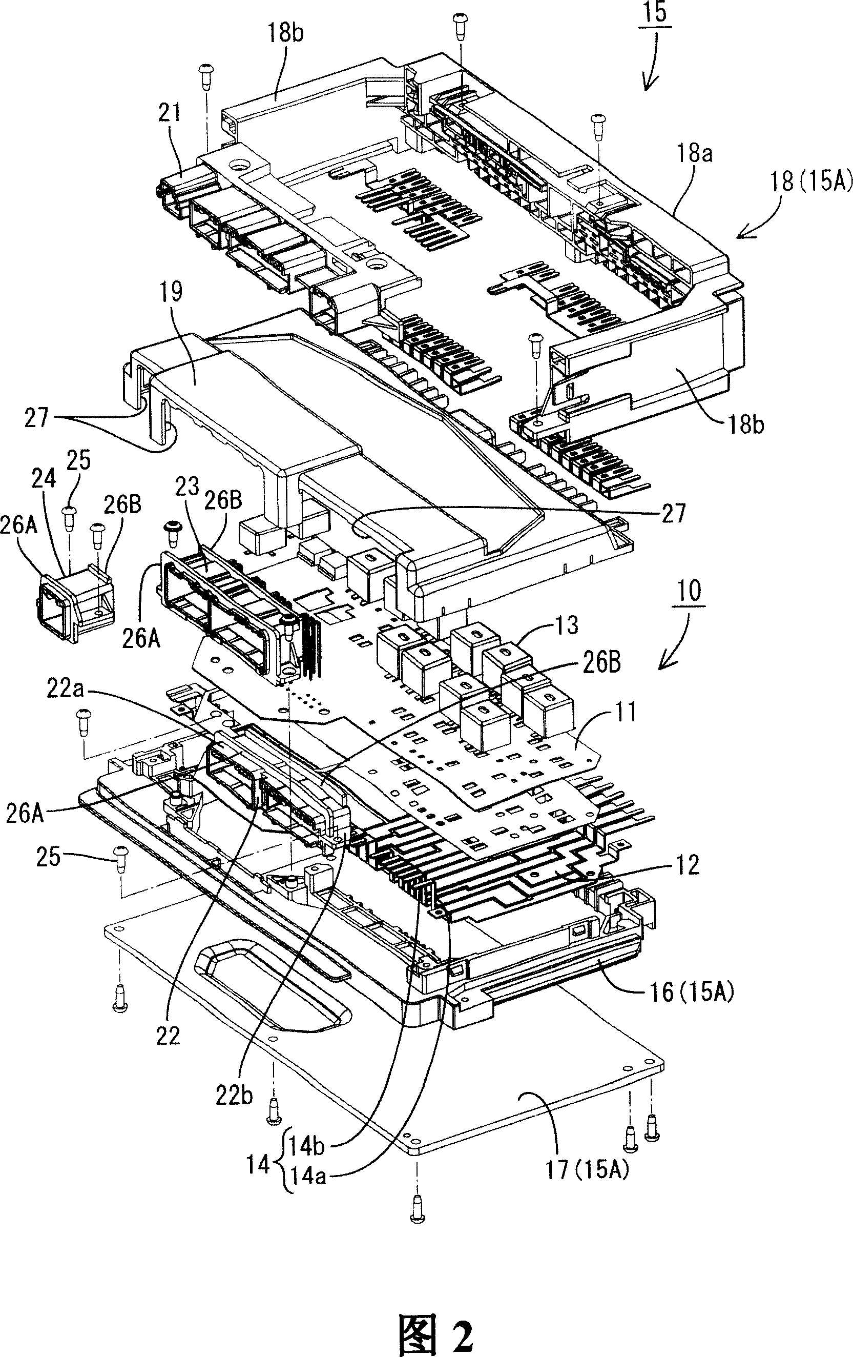
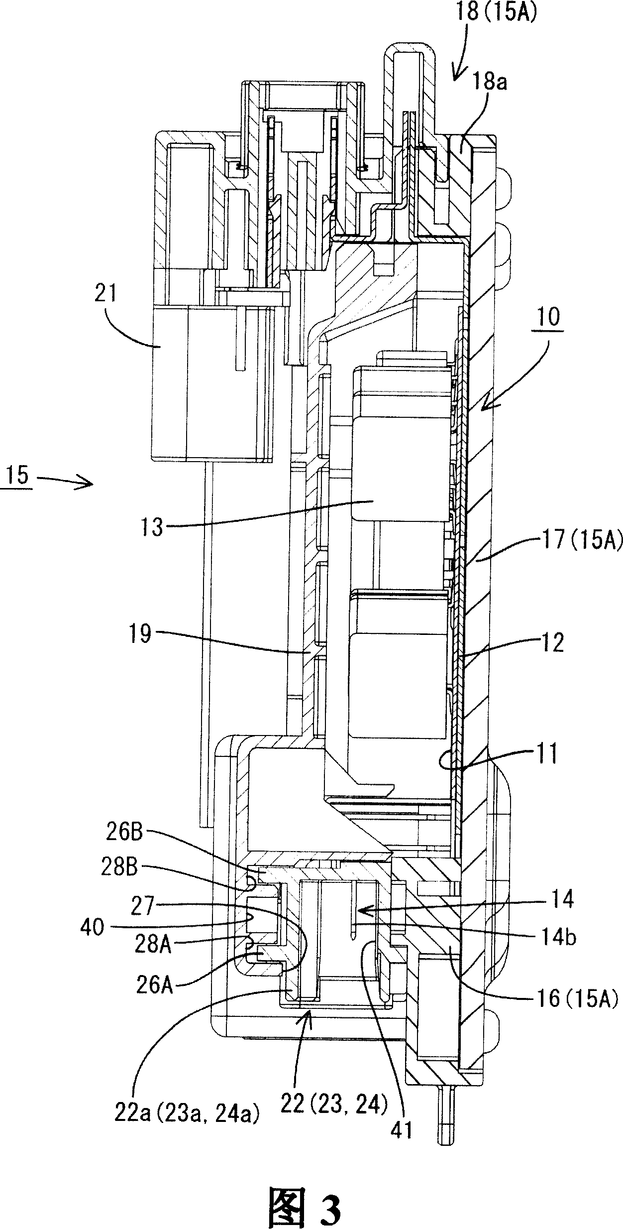
[0013] Hereinafter, an embodiment of the present invention will be described with reference to FIGS. 1 to 3 . The electrical connection box according to this embodiment is mounted on a motor vehicle, and is installed between a battery (not shown) and in-vehicle electrical appliances (not shown) such as lamps and speakers. This electrical connection box distributes / supplies electric power supplied from the battery to each electric appliance, and controls the power supply of these electric power on or off. In addition, in FIG. 1, FIG. 2, the electrical junction box is drawn so that the front side may face upward. However, when mounted on a motor vehicle, as shown in FIG. 3 , the electrical connection box is accommodated in a relay box (not shown) in the following orientation: the fuse box 18 is located on the upper side, and the connectors 21, 22, 23, 24 The fitting opening 41 is opened downward. This relay box is fixed to a vehicle body (not shown). In the following descript...


PUM


Abstract

The box (15) for accommodating the circuit structure (10) has a frame (16) arranged along the periphery of the circuit board (11), and a cover (19) assembled to the frame 16 in a manner covering the circuit board (11). ), the frame body (16) is provided with connectors (22, 23, 24) facing the outer peripheral side of the frame body (16), and on the corresponding surfaces of the cover (19) and the connector (22, 23, 24) , forming a first rib (26A), a second rib (26B), and a first rib accommodating groove that can restrict liquid passing through the gap between the connector (22, 23, 24) and the cover (19) by concave-convex fitting (28A), the second rib accommodating groove (28B), therefore can prevent the liquid outside the frame body (16) from infiltrating into the frame body (16) through the gap between the connectors (22, 23, 24) and the cover (19) Inside.

Description

[0001] This application claims priority from Japanese Patent Application No. 2005-254642 filed on September 2, 2005. Its entire content is therefore included in this application. technical field [0002] The invention relates to an electrical connection box. Background technique [0003] As an electrical connection box mounted on a motor vehicle, there is included a device having a structure in which a circuit structure is accommodated in a box. The circuit structure has a circuit board, a bus bar wired along the back of the circuit board, and switching components such as relays mounted on the front side of the circuit board. Terminals are formed on the bus bar by bending its end into a substantially L-shape. The box includes a frame disposed along the periphery of the circuit board and fixed to the circuit board, and a cover attached to the frame so as to cover the circuit board from the front side. A connector case is attached to the frame so as to face the outer periphe...

Claims


Application Information

Patent Timeline
IPC IPC(8): H02G3/16
CPCH05K5/063H01R13/5202H05K7/026Y10S439/949
Inventor 佐佐木庆一北幸功
Owner AUTONETWORKS TECH LTD
Why Eureka
Try Eureka