
Cutting tool and method for cutting material

A technology for cutting materials and tools, applied in milling cutters, manufacturing tools, twist drills, etc., can solve the problems of insufficient pit accuracy and impossible to provide, and achieve the effect of reducing mechanical stress, vibration and wear

Active Publication Date: 2007-03-14
SANDVIK INTELLECTUAL PROPERTY AB +1
View PDF0 Cites 9 Cited by
  • Summary
  • Abstract
  • Description
  • Claims
  • Application Information

AI Technical Summary

Problems solved by technology

[0006] However, to date it has not been possible to provide corresponding milling cutters primarily designed for axial milling as previously described and having a diameter below 30 mm and much below 30 mm
This is due to the fact that if prior art tools are used at diameters less than 30 mm or even considerably less than 30 mm, when milling sickle-shaped parts of workpieces, especially hard and tough workpieces such as stainless steel, the The asymmetrical force on is so strong that an ordinary milling cutter with a diameter of less than 30 mm will deflect sideways and perpendicular to the direction of the stepping motion of the tool, so that the resulting pockets will become precision not enough

Method used


Image

  • Cutting tool and method for cutting material
  • Cutting tool and method for cutting material
  • Cutting tool and method for cutting material

Examples


Embodiment Construction

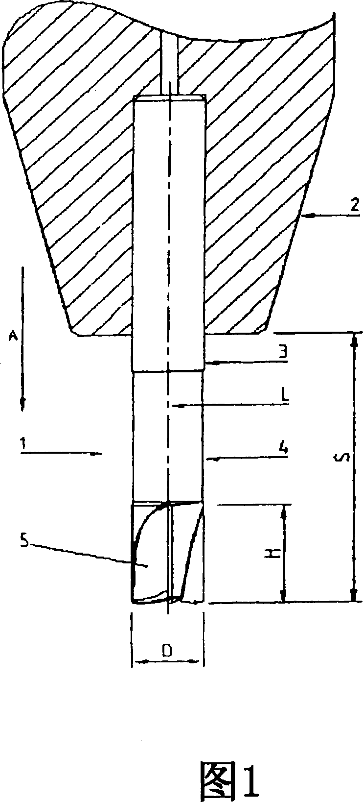
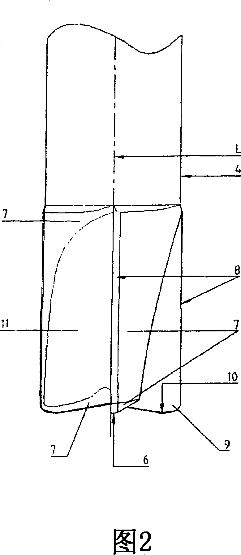
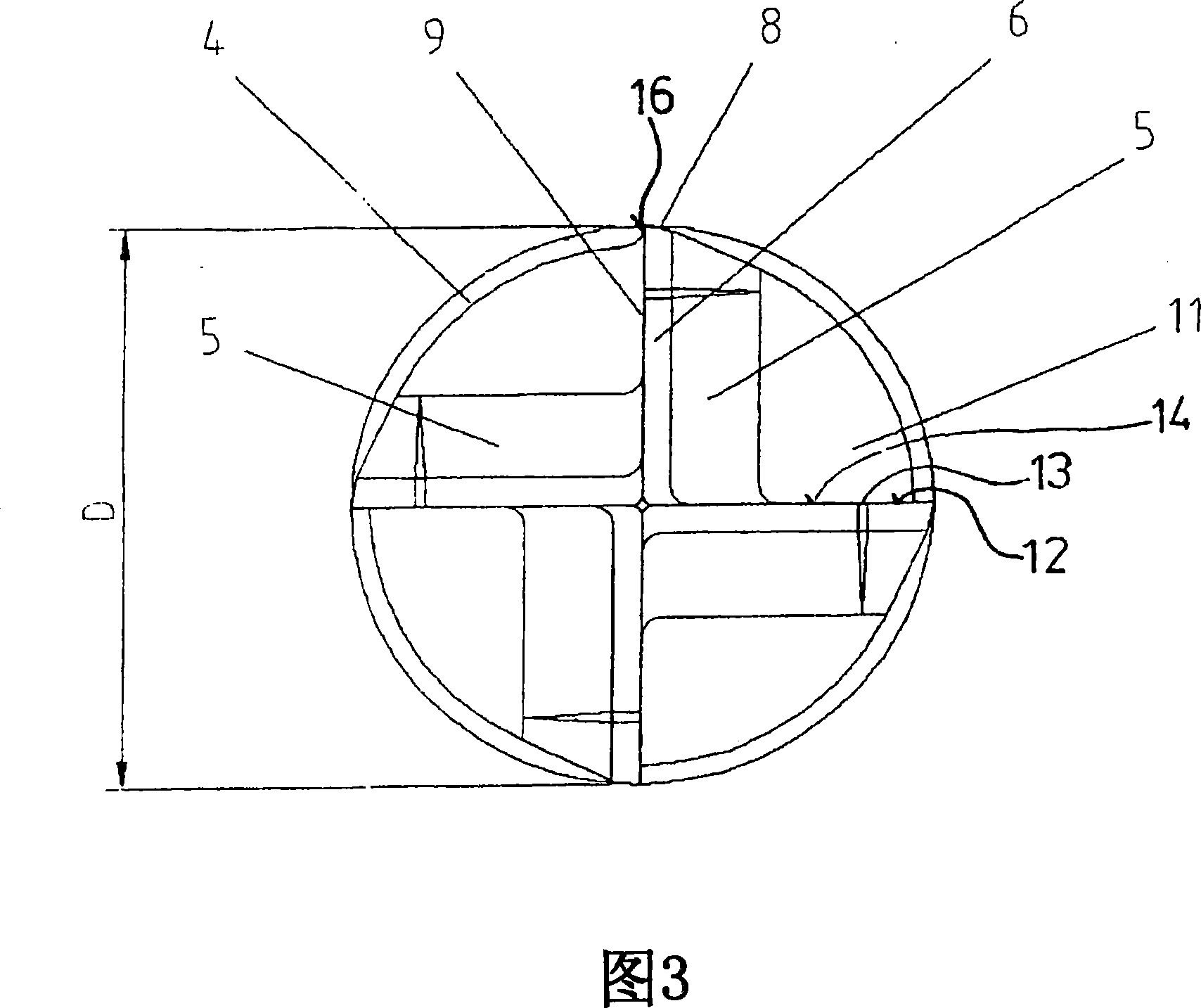
[0033] 1 , 2 and 3 show a cutting tool 1 clamped in a tool holder 2 with a clamping surface 3 . The tool holder 2 is part of a numerically or conventionally controlled machine tool and can position and move the cutting tool towards the part to be machined. In use, the cutting tool 1 is rotated at a rotational speed about an axis of rotation L and is fed at a feed rate A in a feed direction into the material to be cut. The cutting tool 1 is provided with cutting teeth 5 which are connected to the clamping surface 3 via the shank 4 . The number of cutting teeth can vary and generally ranges between two and five, preferably four. The cutting teeth 5 have a cutting diameter D and a cutting height H. On the side remote from the tool holder 4 , ie on the underside, the cutting tooth 5 has a cutting edge 10 for cutting material. Since the cutting edge 10 is at the end of the cutting tool 1, such a tool is also called an end mill. At the periphery, the cutting tooth 5 has a suppor...


PUM


Abstract

Tool for cutting materials with a rotatable body having a rotation axis and cutting edges for cutting the material during movement of the body in a first direction parallel to the rotation axis. In order to stabilise the tool during cutting the cutting edges comprise inner cutting edges laying on a first surface of revolution which is in the first direction higher at a larger diameter and lower at a smaller diameter. The invention includes methods for using the tool.

Description

technical field [0001] The invention relates to a tool for cutting material according to the preamble of claim 1 . Known cutting tools have the disadvantage that when cutting asymmetrical cutting parts, the cutting tool tends to slip to the side in a direction perpendicular to the axis of rotation. This causes problems with insufficient precision and requires that the material must be machined at lower cutting speeds and / or feed rates. [0002] In particular, the invention relates to a cutting tool designed for use as an end mill, wherein, however, said end mill is specially configured for axial milling, ie feed in the axial direction during cutting. Background technique [0003] Axial milling is a cutting operation that is particularly effective for producing deep pockets that require planing away a correspondingly large amount of material. [0004] Usual end mills are only used for a small amount of axial feed, while the main feed direction will be perpendicular to the a...

Claims


Application Information

Patent Timeline
Patent Type & Authority Applications(China)
IPC IPC(8): B23B51/02B23C5/10
Inventor 卡斯滕·京特扬·埃金克扬·范·弗兰肯海策
Owner SANDVIK INTELLECTUAL PROPERTY AB
Learn More