Elevator using cable and method for manufacturing same

An elevator and rope technology, used in textile cables, textiles and paper, coatings, etc., can solve problems such as overall shortening of life, difficult resin thickness, wire wear or breakage, etc.

Inactive Publication Date: 2007-03-14
MITSUBISHI ELECTRIC CORP
View PDF1 Cites 11 Cited by
  • Summary
  • Abstract
  • Description
  • Claims
  • Application Information

AI Technical Summary

Problems solved by technology

[0004] In the above-mentioned conventional elevator ropes, since the sub-ropes are in contact with each other between the layers, the wires are worn or broken, and the overall life may be shortened.
In addition, at the time of manufacture, it is difficult to ensure a stable resin thickness between layers and strands

Method used


Image

  • Elevator using cable and method for manufacturing same
  • Elevator using cable and method for manufacturing same
  • Elevator using cable and method for manufacturing same

Examples


Embodiment approach 1

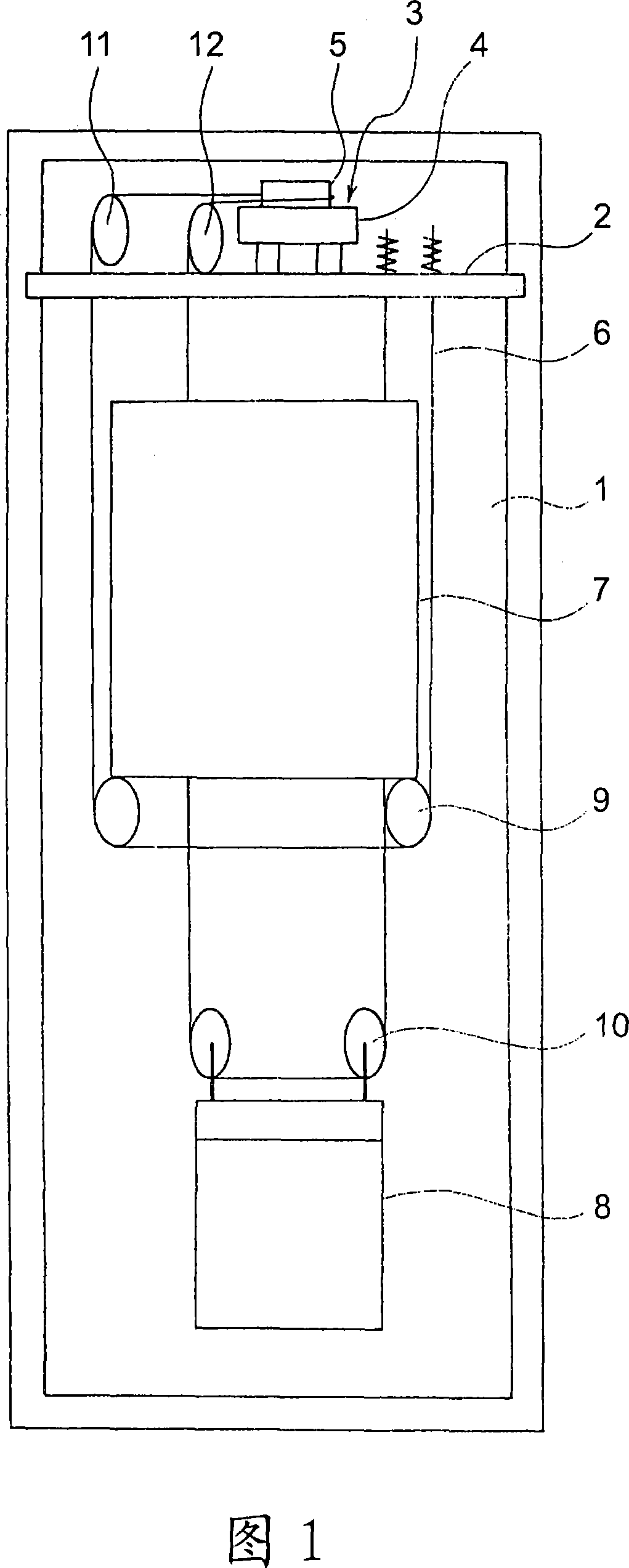
[0017] Fig. 1 is a block diagram showing an elevator apparatus according to Embodiment 1 of the present invention. In the drawing, a supporting beam 2 is horizontally fixed to the upper part in the hoistway 1 . A drive device (tractor) 3 is attached to the support beam 2 . The driving device 3 includes: a driving device main body 4 having a motor; and a driving sheave 5 rotated by the driving device main body 4 . The driving device 3 is arranged horizontally so that the rotation axis of the driving sheave 5 extends vertically.

[0018] A plurality of main ropes 6 serving as elevator ropes are wound around the drive sheave 5 . In FIG. 1, only one main rope 6 is shown for simplicity. Both ends of the main rope 6 are connected to the support beam 2 . The car 7 and the counterweight 8 are suspended in the hoistway 1 by the main rope 6, and are raised and lowered by the driving device 3.

[0019] A pair of car suspension sheaves 9 around which main ropes 6 are wound are provid...

Embodiment approach 2

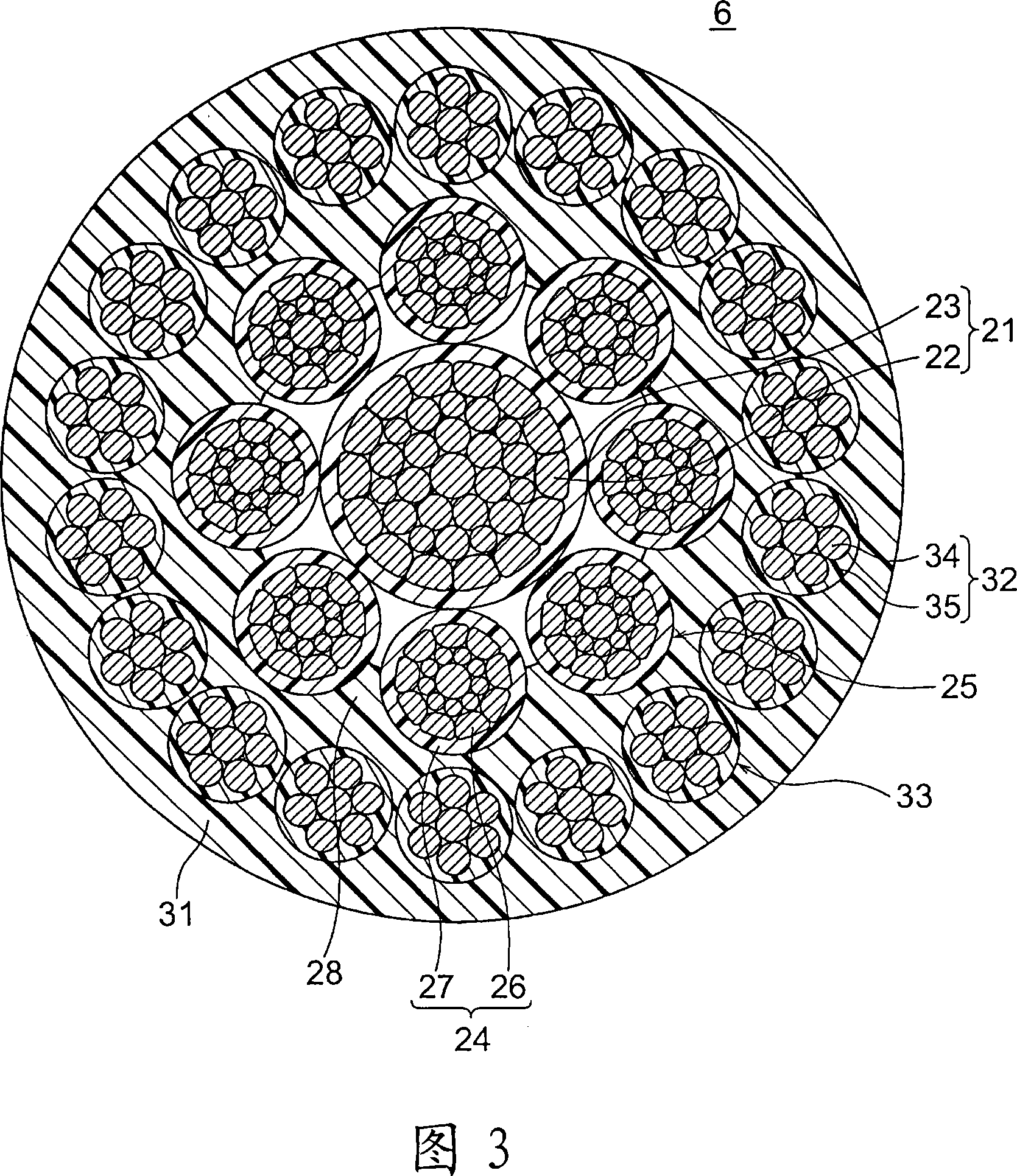
[0036] Next, Fig. 3 shows a cross-sectional view of an elevator rope according to Embodiment 2 of the present invention. In the figure, an outer layer strand aggregate 33 composed of a plurality (here, 20) outer layer strands 32 is arranged on the outer periphery of the inner layer covering body 28 . The outer layer strands 32 are twisted around the outer periphery of the inner layer covering body 28 . In Embodiment 2, each outer layer strand 32 has an outer layer strand main body 34 formed by twisting a plurality of steel wires; Overlay 35.

[0037] FIG. 4 is an enlarged cross-sectional view of the outer layer strand 32 in FIG. 3 . Between the outer layer strand main body 34 and the outer layer strand covering body 35 , and between the steel wires constituting the outer layer strand main body 34 , are bonded by an adhesive 36 . In addition, as shown in FIG. 5 , an adhesive 36 is applied to the outer circumference of each outer layer strand 32 , that is, the outer circumfer...

Embodiment approach 3

[0043] Next, Fig. 6 is a cross-sectional view of an elevator rope according to Embodiment 3 of the present invention. In this example, an extremely thin resin film is interposed between adjacent inner layer strands 24, or adjacent inner layer strands 24 are brought into direct contact with each other. In addition, an extremely thin resin film is interposed between adjacent outer layer strands 32, or adjacent outer layer strands 32 are brought into direct contact with each other. The cross-sectional shapes of the inner layer strand wrapping body 27 and the outer layer strand wrapping body 35 are substantially trapezoidal with rounded corners so as to sufficiently secure the contact area between the adjacent wrapping bodies 27 and 35 . Such a cross-sectional structure can be realized, for example, by applying heat or pressure when twisting the inner layer strands 24 and the outer layer strands 32 . Other structures are the same as those in Embodiment 2.

[0044] In such an ele...


PUM

PropertyMeasurementUnit
friction coefficientaaaaaaaaaa

Abstract

A rope for elevator in which a core rope comprises a core rope body, and its resin core rope coating. An inner layer strand aggregate comprises a plurality of inner layer strands stranded around the core rope on the outer circumference thereof. Each inner layer strand comprises an inner layer strand body, and its resin inner layer strand coating. An outer layer strand aggregate comprises a plurality of outer layer strands stranded on the outer circumference of the inner layer strand aggregate. Each outer layer strand has an outer layer strand body. The outer layer strand aggregate is coated with a resin outer layer coating. The inner layer strand body and the inner layer strand coating are bonded through adhesive, and the outer layer strand and the outer layer coating are bonded through adhesive.

Description

technical field [0001] The present invention relates to an elevator rope provided with a resin outer covering body on the outer periphery thereof and a method for manufacturing the same. Background technique [0002] In existing elevator ropes, the inner layer rope has a plurality of inner layer sub-ropes twisted from a plurality of steel wire rods. The outer periphery of the inner layer rope is covered with a resin inner layer covering body. An outer layer is provided on the outer peripheral portion of the inner layer covering body. The outer layer has a plurality of outer layer sub-ropes twisted by a plurality of steel wire rods. The outer periphery of the outer layer is covered with an outer layer covering body made of a high-friction resin material (for example, refer to Patent Document 1). [0003] Patent Document 1: WO03 / 050348A1 [0004] In the above-mentioned conventional elevator ropes, since the strands contact each other between the layers, the wires are worn ...

Claims


Application Information

Patent Timeline
Patent Type & Authority Applications(China)
IPC IPC(8): B66B7/06
CPCD07B1/162D07B2501/2007B66B7/06D07B2201/2044D07B2201/1036D07B2201/2046D07B1/167D07B1/165
Inventor 本田武信光井厚
Owner MITSUBISHI ELECTRIC CORP
Why Eureka
Try Eureka