Top air intake gas stove burner

A gas cooker and burner technology, which is applied in the direction of gas fuel burners, burners, combustion methods, etc., can solve the problems of complex manufacturing process and low combustion efficiency, and achieve the effect of simple manufacturing process and accelerated fluidity

Inactive Publication Date: 2007-03-21
谭六明
View PDF0 Cites 20 Cited by
  • Summary
  • Abstract
  • Description
  • Claims
  • Application Information

AI Technical Summary

Problems solved by technology

[0003] The purpose of the present invention is to solve the problems of complex manufacturing process and low combustion efficiency in the existing gas cooker burner with upward air intake, and to provide an upward air intake gas cooker burner with simple manufacturing process and high combustion efficiency

Method used


Image

  • Top air intake gas stove burner
  • Top air intake gas stove burner
  • Top air intake gas stove burner

Examples


Embodiment Construction

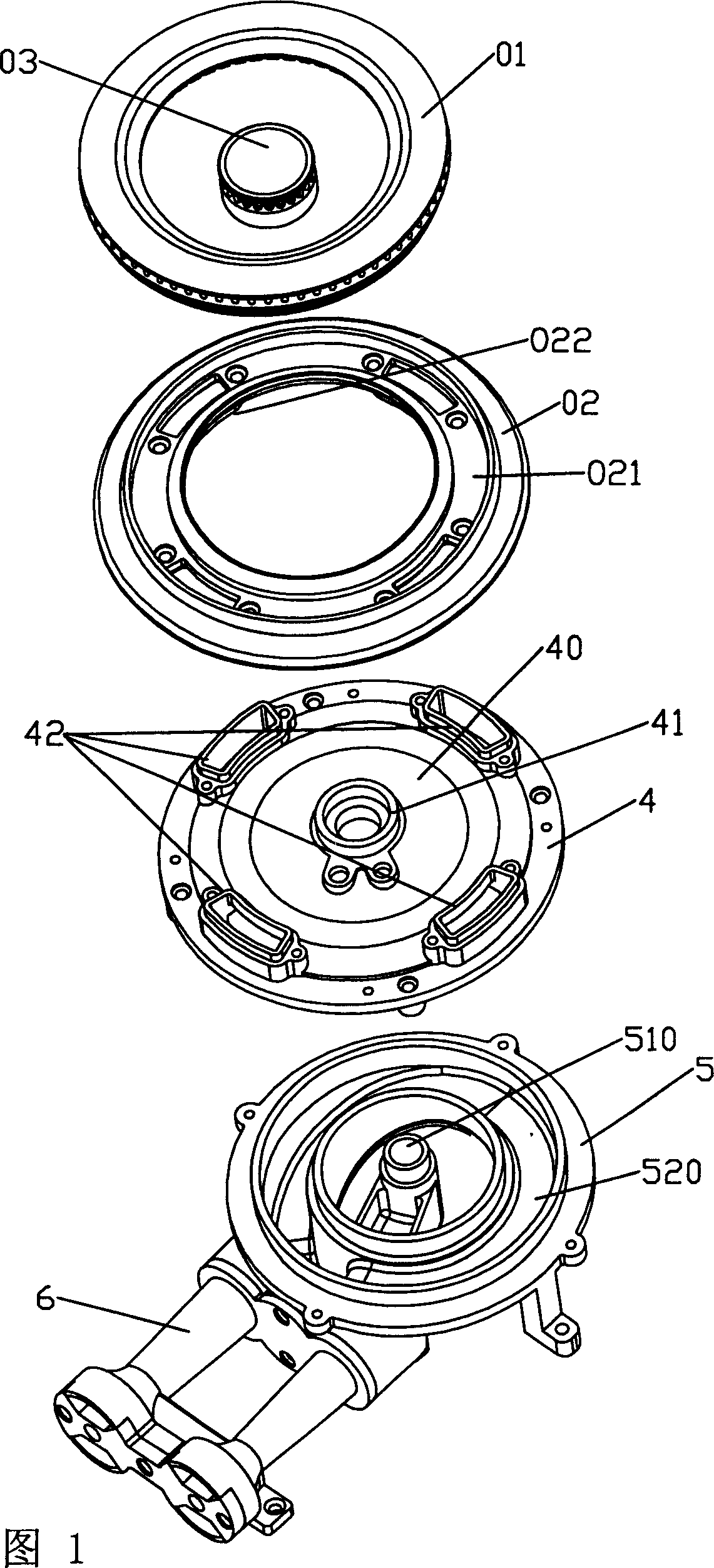
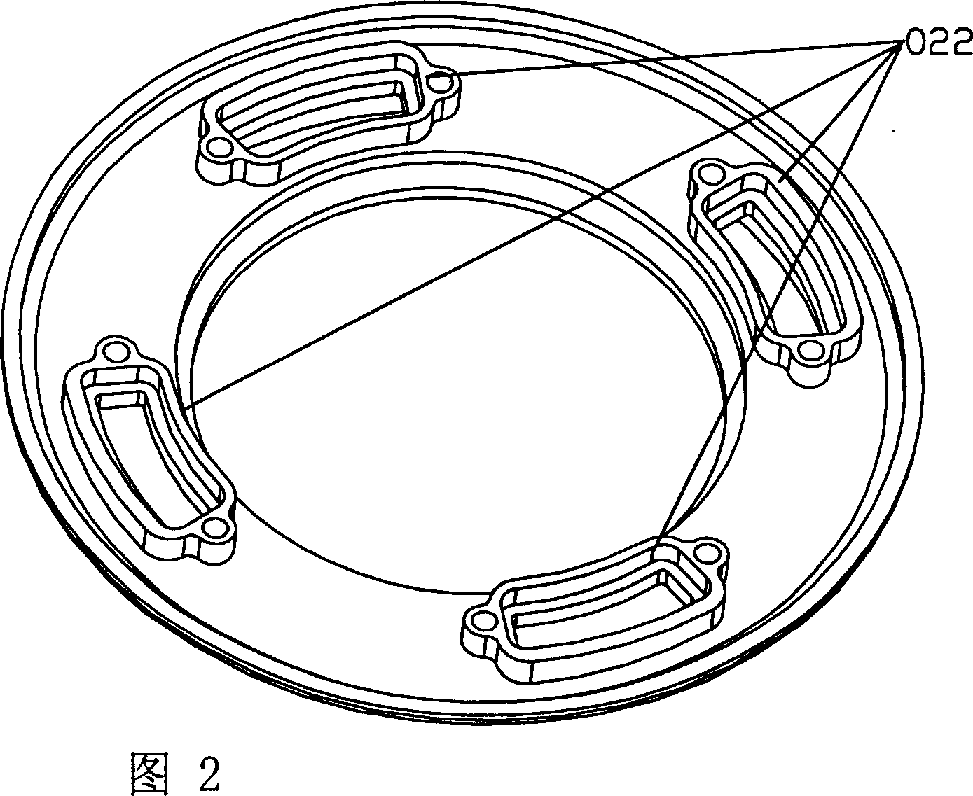
[0020] As shown in Fig. 1, the gas cooker burner with air intake from above includes an outer fire cover 01, an outer ring fire cover seat 02, a chassis 4 and a burner 5 arranged sequentially from top to bottom, and the chassis 4 and the burner top are ring-shaped. The outer ring gas mixing groove 520 constitutes the first gas mixing chamber 500 shown in FIG. Cavity 200, four evenly distributed inlet flanges 022 are arranged on the lower side of the outer ring fire cover seat 02 (see Figure 2 for details), and an outlet flange 42 corresponding to and matched with the inlet flange 022 is arranged on the upper side of the chassis. As shown in Fig. 4, the first gas mixing chamber 500 communicates with the second gas mixing chamber 200 through the gas outlet flange 42 and the inlet flange 022; a central pipe 510 communicated with the central gas channel is provided in the center of the burner, and the central pipe 510 is connected to the chassis 4. The flanges are connected betwee...


PUM


Abstract

The present invention relates to a gas cooker burner into which the air can be fed from top portion. It includes successively-arranged outer fire lid, outer ring fire lid seat, base plate and stove head with injection tube from top to bottom, and it is characterized by that the base plate and circular outer-ring gas-mixing channel on the stove head are formed into first gas mixing cavity, the circular outer fire lid and outer ring gas channel or outer ring fire lid seat are formed into second gas mixing cavity. Besides, it also includes air inlet flange and air outlet flange. Said invention is simple in structure and its combustion efficiency is high.

Description

technical field [0001] The invention relates to a gas cooker burner, in particular to an upward air-flow gas cooker burner. Background technique [0002] The existing gas cooker burner with upward air intake includes a burner head, a central fire cover and an outer fire cover. The central air passage and the outer ring fire gas groove are directly arranged on the burner head, and the central fire cover covers the outlet of the central air passage. After the cover covers the outer ring gas groove, it forms the outer ring fire gas channel with the outer ring fire gas groove, in which the central fire gas channel and the outer ring fire gas channel are respectively connected with the gas valve through the air-introducing pipe. , because the central gas channel and the outer ring fire gas channel are directly arranged on the burner head, so the manufacturing process of the burner head is complicated, the production efficiency is low, and the gas and air are not mixed sufficientl...

Claims


Application Information

Patent Timeline
Patent Type & Authority Applications(China)
IPC IPC(8): F23D14/06F23D14/62
Inventor 谭六明
Owner 谭六明
Why Eureka
Try Eureka