Cable positioning clamping device and regulation

A clamping device and cable technology, which is applied in the direction of cable/conductor manufacturing, electrical components, circuits, etc., can solve the problems that the 360-degree circumferential force of the cable cannot be guaranteed to be uniform, affect the wrapping quality, and restrict the production speed, etc. , to achieve the effect of small friction, no temperature rise and reliable operation

Inactive Publication Date: 2007-03-21
百通赫思曼工业(苏州)有限公司
View PDF0 Cites 9 Cited by
  • Summary
  • Abstract
  • Description
  • Claims
  • Application Information

AI Technical Summary

Problems solved by technology

[0002] In the current wire and cable equipment and cable production industry, single stranding machine, cage stranding machine and other cable forming equipment prevent the cable from shaking or being scratched when producing wire and cable. In order to make the cable have better positioning and smooth movement, Both use metal eye molds with cylindrical holes slightly larger than the cable diameter, tungsten steel molds, nylon eye molds or use three guide rollers (two vertically, one horizontally) to fix and clamp the cable. There are deficiencies in these existing technologies: on the one hand, it is necessary to select eye molds with different hole diameters for the production of different wire diameters, and the use of three guide roller support structures is inconvenient to adjust and unstable in structure; on the other hand, after long-term use The hole of the eye die is severely worn, and more importantly, when the produced wire needs to be wrapped with aluminum platinum or polyester tape by the wrapping machine, due to the certain tension of the wrapping, the cable will be pulled by the wrapping tape and shake 360 ​​degrees. In addition, long-term production eye mold friction will cause temperature rise, which will also affect the wrapping quality and restrict the production speed, and the structure of the three guide roller brackets cannot ensure that the 360-degree circumferential force of the cable is uniform, so the wire during the cable production process The problem of cable positioning and clamping technology has been plagued by technical personnel in the industry

Method used


Image

  • Cable positioning clamping device and regulation
  • Cable positioning clamping device and regulation

Examples


Embodiment Construction

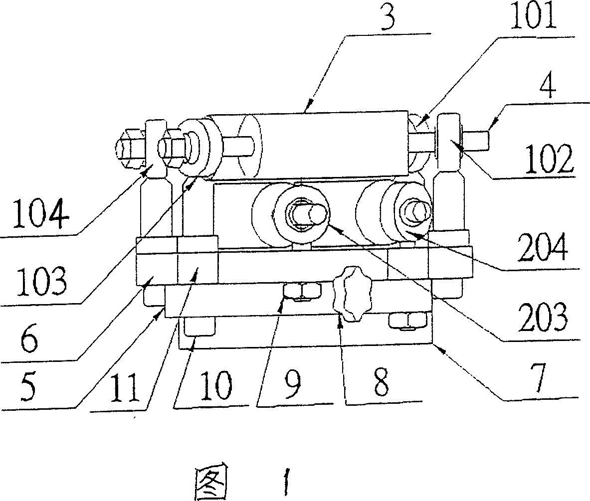
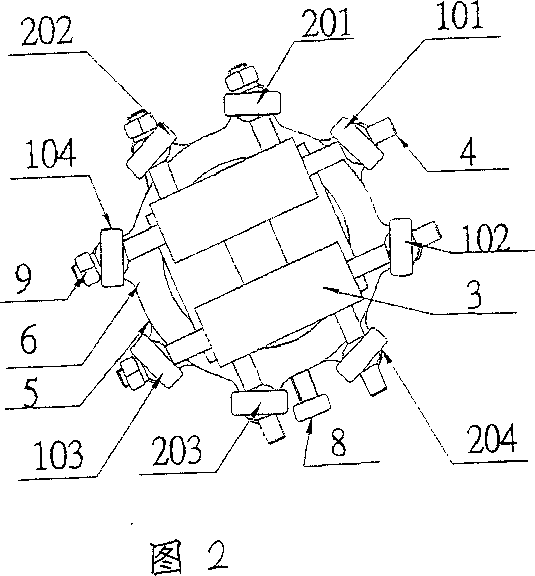
[0009] The present invention will be further described with reference to accompanying drawing 1 and Fig. 2 and embodiment:

[0010] This embodiment is a cable positioning and clamping device with a well-shaped guide wheel frame whose through hole diameter can be adjusted within the range of 0 mm to 28 mm. All components are installed according to the structure in the accompanying drawings. Among them: joint bearings 201, 203, 102, and 104 are installed on the fixed seat 6 with an outer diameter of φ80mm, an inner hole of φ36mm, a thickness of 20mm (including ring-shaped steps with a thickness of 10mm and φ60mm), and a distance between the center holes of the upper and lower or left and right lugs of 93mm. On, the joint bearings 202, 204, 101, 103 are installed on the movable seat 5 with an outer diameter of φ80mm, an inner hole of φ60mm, a thickness of 10mm, and a distance between the center holes of the upper and lower or left and right lugs of 93mm. A washer 11 with an outer...


PUM


Abstract

Cable location and holding equipment and adjust method use for single twist cabling machine and cage stranger. Existing technology adopts eye mould or three guiding rolls, but its adjust isn't easy and the eye mould easily wear out with friction and warm up. In this paper, a well style cable location and holding equipment is made up of four active guiding rolls and relates to inner rifled self-assembly pole-end joint bearing, outside rifled self-assembly pole-end joint bearing, guiding roll combination,guiding roll axes,active seat,up and down fix seat and revolving handle bolt. During the adjust, positive and negative revolving active seat adjusts cable passing hole, adjusts the foursquare hole in the middle of well style made up by parallel guiding roll axes. It saves cost and adjusts easily with credible operation and without continually changing eye mould. Four idler pulleys in well style move with credible with small friction and without warm up to keep each capability of credible.

Description

technical field [0001] The invention relates to the technology of wire and cable production equipment, in particular to the technology of positioning and clamping devices used in the production of cable equipment such as single stranding machine and cage stranding machine in the production equipment. Background technique [0002] In the current wire and cable equipment and cable production industry, single stranding machine, cage stranding machine and other cable forming equipment prevent the cable from shaking or being scratched when producing wire and cable. In order to make the cable have better positioning and smooth movement, Both use metal eye molds with cylindrical holes slightly larger than the cable diameter, tungsten steel molds, nylon eye molds or use three guide rollers (two vertically, one horizontally) to fix and clamp the cable. There are deficiencies in these existing technologies: on the one hand, it is necessary to select eye molds with different hole diame...

Claims


Application Information

Patent Timeline
Patent Type & Authority Applications(China)
IPC IPC(8): H01B13/02H01B13/00
Inventor 朱一夫付宽林蒋留稳张涛
Owner 百通赫思曼工业(苏州)有限公司
Why Eureka
Try Eureka