Coil terminal assembly for magnetic contactor

A technology of coil end and magnetic contact, which is applied to the components of relays, electromagnetic relays, details of electromagnetic relays, etc., and can solve problems such as difficulty in driving screw rotation

Inactive Publication Date: 2007-03-21
LSIS CO LTD
View PDF1 Cites 5 Cited by
  • Summary
  • Abstract
  • Description
  • Claims
  • Application Information

AI Technical Summary

Problems solved by technology

As a result, the thread of the body portion 32 of the driving screw 30 is not fully engaged with the threaded portion 10a of the connection holder 10, which makes it difficult to rotate the driving screw.

Method used


Image

  • Coil terminal assembly for magnetic contactor
  • Coil terminal assembly for magnetic contactor
  • Coil terminal assembly for magnetic contactor

Examples


Embodiment Construction

[0034] Reference will now be made in detail to the preferred embodiments of the present invention, examples of which are illustrated in the accompanying drawings.

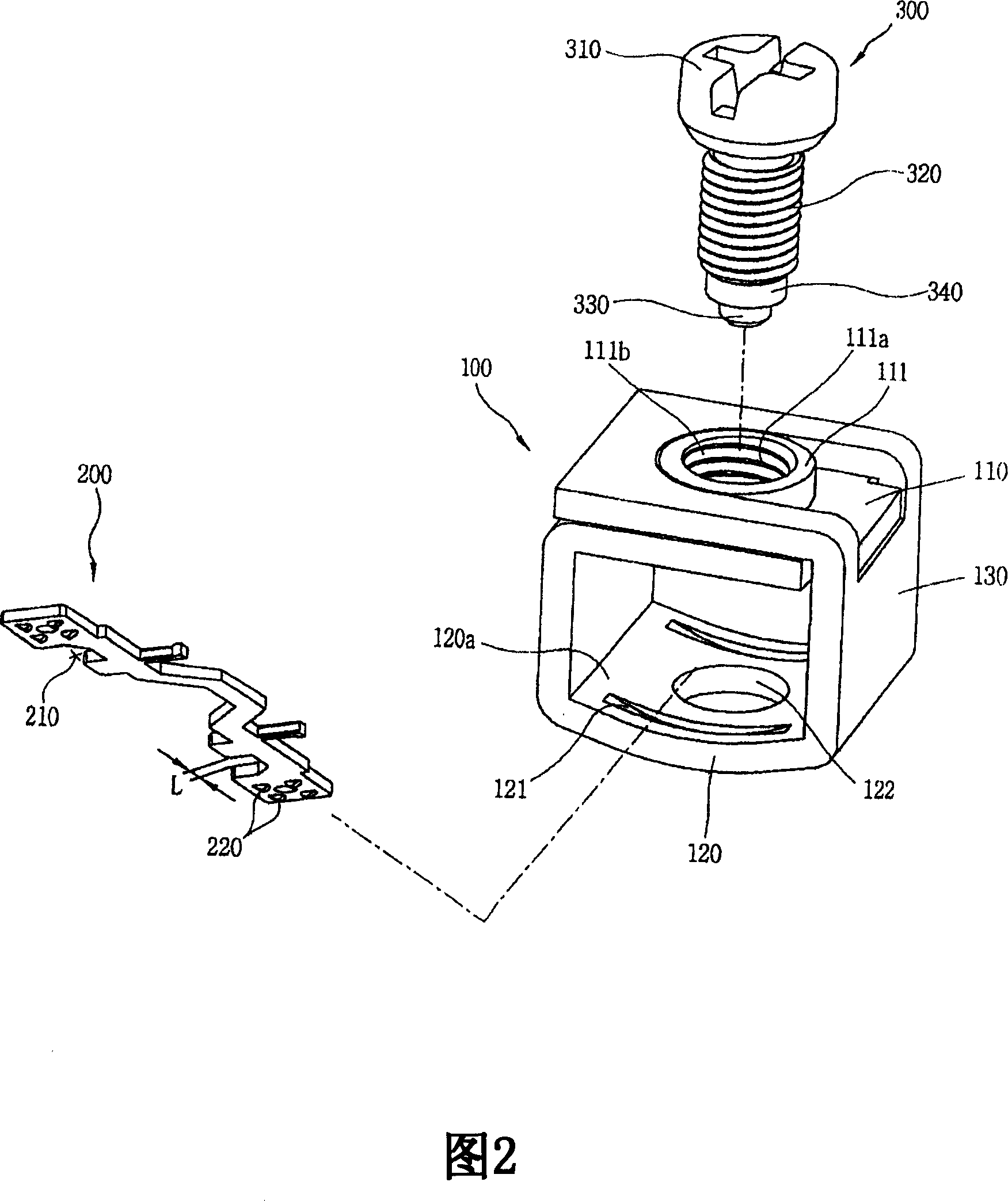
[0035] A coil end assembly for a magnetic contactor according to the present invention is installed at the magnetic contactor. The magnetic contactor includes a well-known conductive part (not shown) having a stationary contact (not shown) and a movable contact (not shown) which moves to contact or separate from the stationary contact; and a coil mechanism (indicating is the number 400 in Fig. 5), which provides the driving force for driving the movable contact. The appearance of the magnetic contactor according to the present invention can refer to the accompanying drawing 4 .

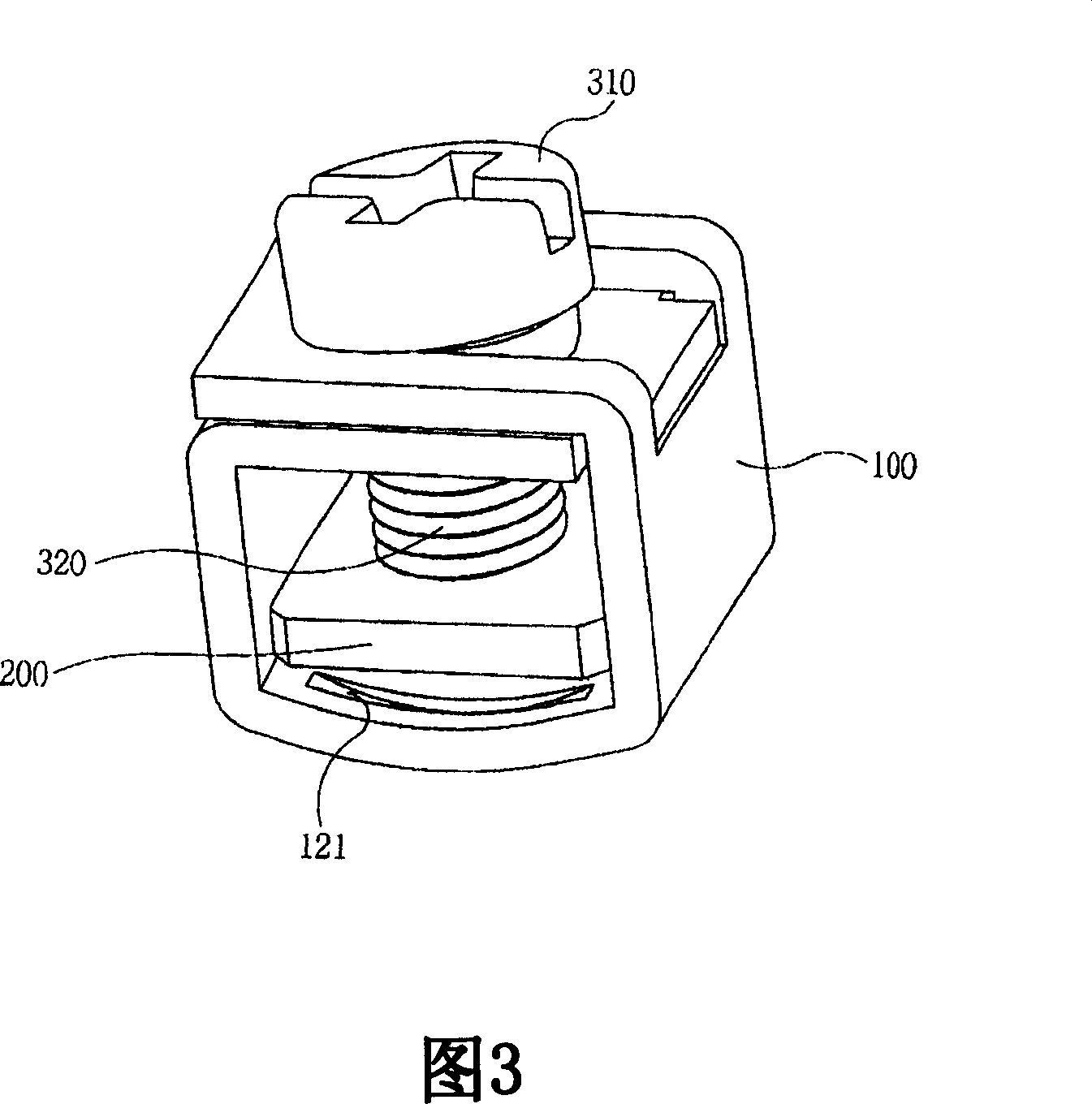
[0036] Referring to FIG. 2 , a coil end assembly for a magnetic contactor according to the present invention includes a coil end 200 . The coil end 200 is connected to the coil 400a of the coil structure 400 in FIG. 5 . The coil end 200...


PUM


Abstract

A coil terminal assembly for a magnetic contactor comprises: a coil terminal connected to the coil and electrically connected to an external wire, for magnetizing the coil thereby driving the movable contact; a connection supporting member having a top portion having a threaded screw connection portion, a body portion having an opening through which the coil terminal and the external wire are inserted and providing a space in which the coil terminal and the external wire are electrically connected to each other, and a bottom portion formed as a concave surface inclined towards a center portion, the connection supporting member movable to a position for pressurizing the external wire so as to maintain an electrical connection between the external wire and the coil terminal, and movable to a position for separating the external wire from the coil terminal; and a driving screw having a threaded surface meshed with the screw connection portion, for driving the connection supporting member along the threaded surface.

Description

[0001] related application [0002] The present disclosure is related to subject matter contained in prior Korean Patent Application No. 10-200500085351 filed Sep. 13, 2005, the entire contents of which are hereby incorporated by reference. technical field [0003] The present application relates to a coil end assembly of a magnetic contactor, in particular to a coil end assembly of a magnetic contactor, which can prevent external wires from being separated from a connection supporting part that connects the coil end of the magnetic contactor to an external Lead wire, and the drive screw that can prevent the connection support member from moving vertically by bending the connection support member when the thick wire is used as an external lead is difficult to drive. Background technique [0004] Generally, a magnetic contactor includes a switch mechanism having a stationary contact and a movable contact that moves to contact or separate from the stationary contact; and a coi...

Claims


Application Information

Patent Timeline
Patent Type & Authority Applications(China)
IPC IPC(8): H01H45/00H01H45/14H01H50/00H01H50/14
CPCH01H2001/5861H01R4/36H01H50/443H01H45/14H01R4/30H01R4/304H01H50/14
Inventor 金俊镐
Owner LSIS CO LTD
Why Eureka
Try Eureka