Domestic network equipment integrated with alarming function and alarming via the same

A technology of home network and equipment, applied in branch offices providing special services, telephone communication, electrical components, etc.

Active Publication Date: 2007-03-21
GLOBAL INNOVATION AGGREGATORS LLC
View PDF0 Cites 4 Cited by
  • Summary
  • Abstract
  • Description
  • Claims
  • Application Information

AI Technical Summary

Problems solved by technology

[0006] The purpose of the present invention is to provide a home network device with an integrated alarm function and a method for alarming thr

Method used


Image

  • Domestic network equipment integrated with alarming function and alarming via the same
  • Domestic network equipment integrated with alarming function and alarming via the same
  • Domestic network equipment integrated with alarming function and alarming via the same

Examples


Embodiment Construction

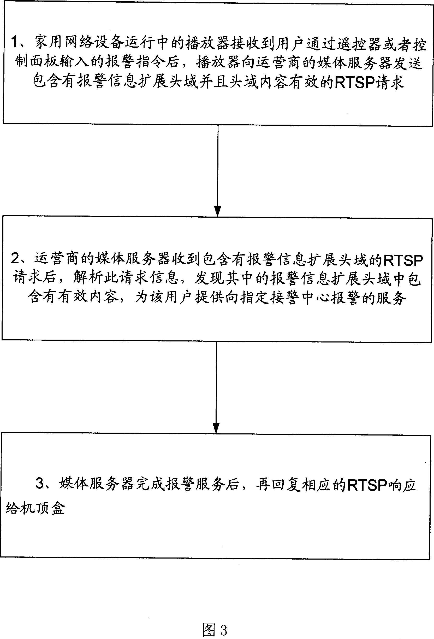
[0034] The basic principle of the present invention is to utilize the home network equipment (such as home gateway and IPTV, etc.) After the home network device receives the instruction, it will start the corresponding remote alarm program, send an alarm message to the designated alarm center, and perform other related operations, such as turning on the home camera device according to the settings.

[0035] A detailed description will be given below in conjunction with the accompanying drawings and specific embodiments.

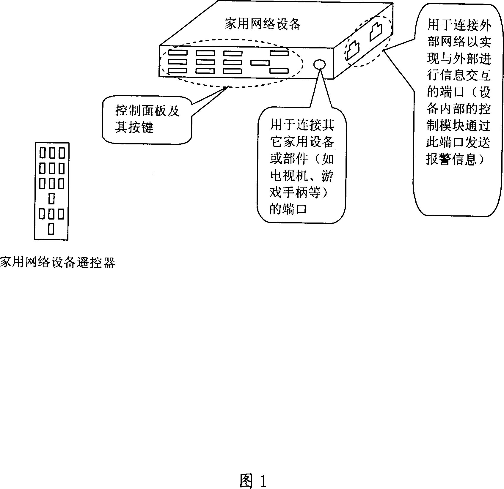
[0036] The home network device described in the embodiment of the present invention is shown in Figure 1, including:

[0037] Remote control or panel control components, used for users to input alarm commands;

[0038] The control module is used to send alarm information to a designated alarm center according to an alarm command input by a user.

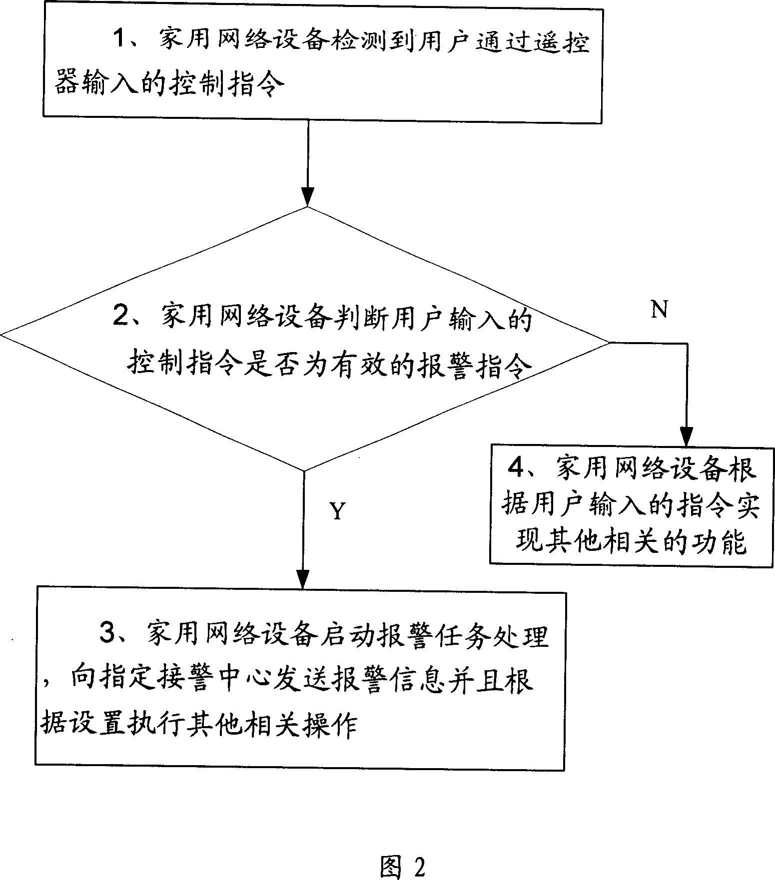
[0039] The flow chart of the embodiment of the present invention is shown in Figure 2, which specifically inclu...


PUM


Abstract

A method of utilizing domestic network equipment to make alarm send alarm information to assigned alarm processing center when alarm command inputted by remote controller of said equipment or by control component on panel of said equipment is received by domestic network equipment.

Description

technical field [0001] The present invention relates to the technical field of home network equipment, in particular, to the technology of alarming through home network equipment. Background technique [0002] At present, when people encounter danger at home, they usually can only call the community center or the police station to the police, and some can also transmit the alarm information through special alarm monitoring equipment, but the concealment of the telephone alarm method is not good, and it is not very convenient. Monitoring equipment requires a certain cost. [0003] The popularization of home network and the emergence of home network terminals such as home gateway and IP set-top box (also known as network set-top box, referred to as IP STB) have made TVs and other home network devices that can only receive information have the ability to send information outside the home. [0004] Among them, the home gateway is the connection point between the home's internal...

Claims


Application Information

Patent Timeline
IPC IPC(8): H04L12/16H04M11/02
Inventor 徐友仁
Owner GLOBAL INNOVATION AGGREGATORS LLC
Why Eureka
Try Eureka