Solid cone spray nozzle

A full cone, nozzle technology, applied in the direction of injection device, injection device, liquid injection device, etc., can solve the problems of continuous casting billet shell cracks, increase the risk of clogging, etc., achieve uniform fluid distribution, reduce the risk of clogging, and improve Effect of flow cross section

Active Publication Date: 2007-03-28
LECHLER SPA
View PDF2 Cites 11 Cited by
  • Summary
  • Abstract
  • Description
  • Claims
  • Application Information

AI Technical Summary

Problems solved by technology

This results in a smaller nozzle cross-section for a given quantity of water to be applied and thus an increased risk of clogging
If the intermediate space between the two guide rollers is not c

Method used


Image

  • Solid cone spray nozzle
  • Solid cone spray nozzle
  • Solid cone spray nozzle

Examples


Embodiment Construction

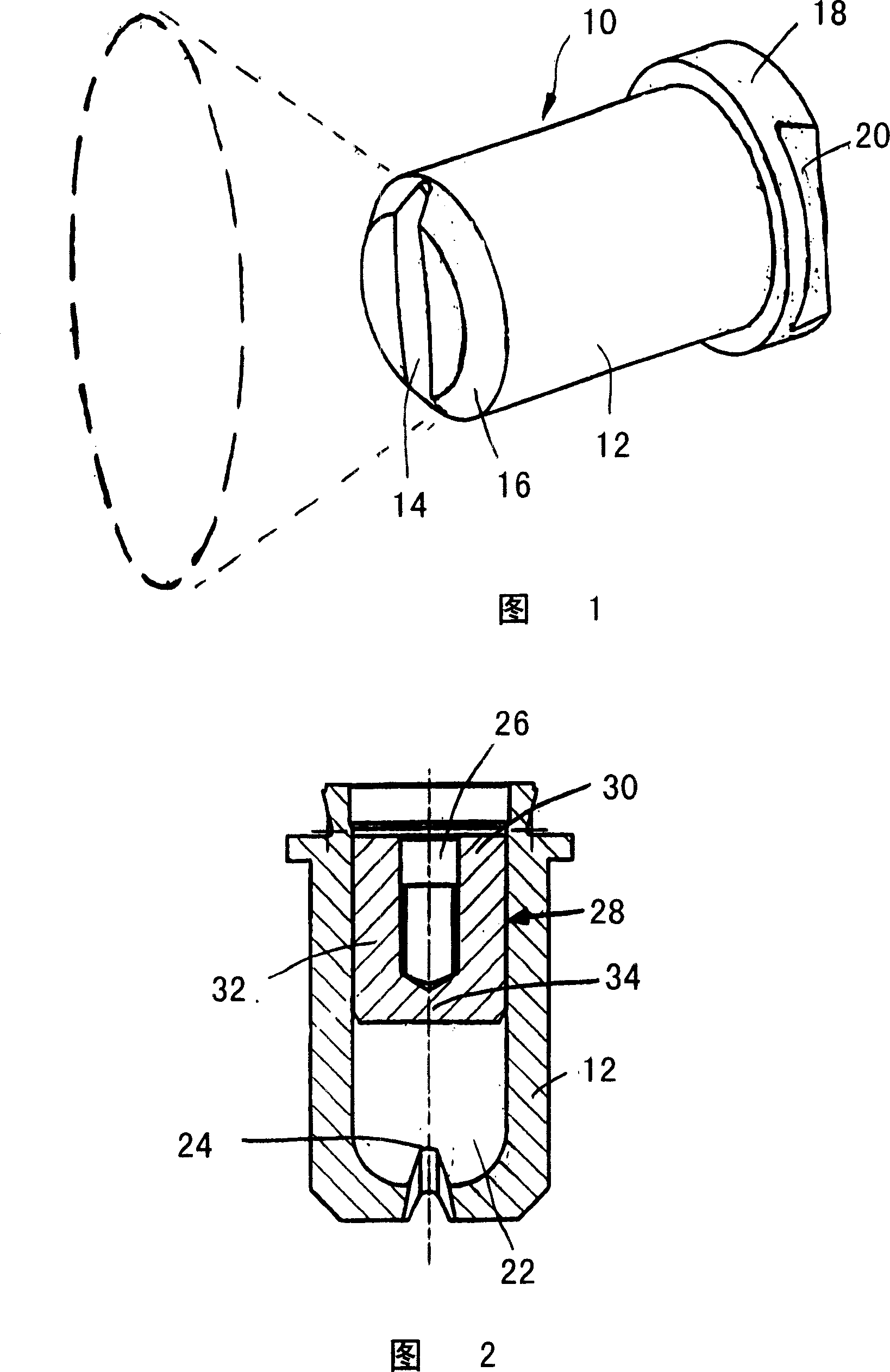
[0062] The perspective view of FIG. 1 shows a spray nozzle 10 according to the invention with an integral spray body housing 12 . An outlet cone 14 can be seen in an end face of the nozzle housing 12 , which adjoins an oval outlet opening, which is not visible in FIG. 1 . The discharge cone 14 has an essentially likewise elliptical cross-sectional shape, wherein this cannot be easily seen in the illustration in FIG. Discharge the side end of the cone.

[0063] The spray body housing 12 is generally cylindrical and has a circumferential flange 18 at its rear end, the end for connection to a fluid line. The flange 18 is laterally provided with flattened sections 20 , of which only one flattened section is visible in the illustration in FIG. 1 , but it covers the opposite identical flattened section.

[0064] A spray cone produced by spray nozzle 10 is indicated by a dashed line in FIG. 1 . As can be seen, the spray cone has a uniform oval shape.

[0065] The jet body housing...


PUM


Abstract

The invention relates to a solid cone spray nozzle with a mouthpiece having an outlet chamber and an inlet opening emanating from the outlet chamber and having a smaller cross-section than the latter. According to the invention an inlet opening into the outlet chamber has a smaller cross-section than the outlet chamber and downstream of the outlet chamber inlet opening is provided a web-like preatomizer element on which impacts at least partly a fluid jet following entry into the outlet chamber. Use e.g. as a two-fluid spray nozzle for spraying or atomizing low viscosity liquids for cooling purposes in billet or bloom continuous casting installations.

Description

technical field [0001] The invention relates to a full-cone nozzle, in particular for atomizing low-viscosity liquids for cooling in a billet caster or bloom caster, the spray nozzle having a spray body, the spray body There is an outlet chamber and an outlet from the outlet chamber, which has a smaller cross-section than the outlet chamber. Background technique [0002] A two-component full-cone nozzle is known from European patent document EP 1243343 B1, which is used for cooling in continuous casting machines. A spout body of this nozzle has an outlet chamber with an outlet opening emanating from the outlet chamber, which has a smaller cross-section than the outlet chamber. A vortex insert is arranged in the discharge chamber formed in the discharge body by the opening, by means of which the gas-liquid mixture is placed in a swirl before reaching the discharge orifice, whereby it emerges conically under pressure from the discharge excreted from the body. The eddy curre...

Claims


Application Information

Patent Timeline
IPC IPC(8): B05B1/02B21B45/02B22D11/124
CPCB05B7/0483B05B1/34B05B1/042B05B1/048B05B1/02
Inventor M·利普塔尔M·阿斯特法尔克L·瓦特
Owner LECHLER SPA
Why Eureka
Try Eureka