Resolver external conductor fixing structure

A technology of resolver and external wires, applied in the direction of converting sensor output, instruments, measuring instrument components, etc., can solve the problems of cumbersome preparation and distinction, inconvenient operation, and production obstacles, and achieve easy automatic operation, simplified equipment, and assembly easy effect

Inactive Publication Date: 2007-03-28
TAMAGAWA SEIKI CO LTD +1
View PDF1 Cites 27 Cited by
  • Summary
  • Abstract
  • Description
  • Claims
  • Application Information

AI Technical Summary

Problems solved by technology

Therefore, in the assembly line, in all processes including the winding process, the lead wires are always connected to the assembly line. Therefore, this operation is inconvenient, and there is a big obstacle in improving productivity.
[0010] In addition, when there are many kinds of lead wires, since the lengths and types of the lead wires are different, it is necessary to prepare various kinds of ring stators with various lead wires installed, and the preparation and differentiation are cumbersome. The variety increases, which becomes a bottleneck in production
[0011] In addition, it is difficult to carry out automatic production according to the specifications required by users

Method used


Image

  • Resolver external conductor fixing structure
  • Resolver external conductor fixing structure
  • Resolver external conductor fixing structure

Examples


Embodiment

[0025] Hereinafter, preferred embodiments of the resolver external wire fixing structure of the present invention will be described with reference to the accompanying drawings.

[0026] In addition, the same reference numerals are used to describe the same or equivalent parts as those in the conventional embodiments.

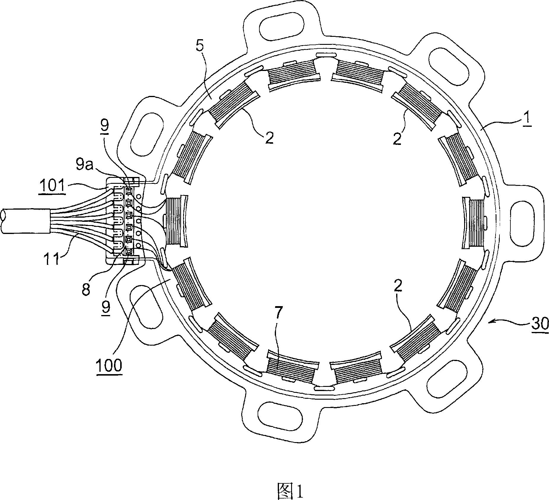
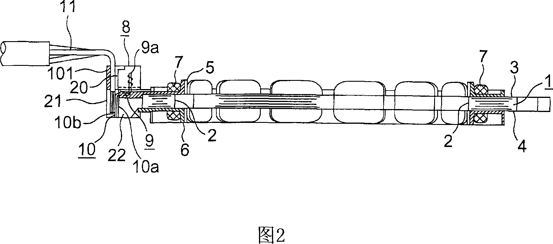
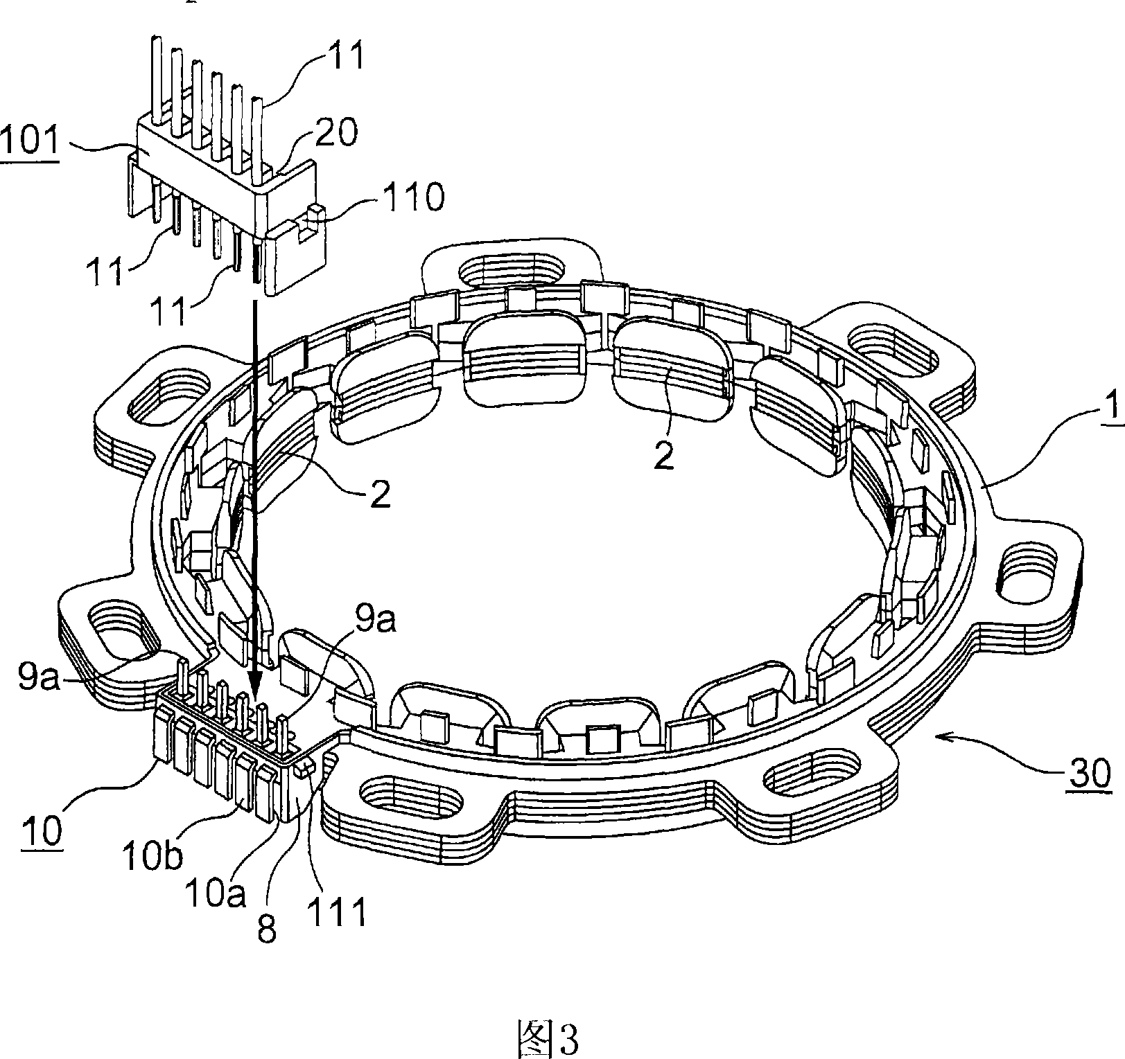
[0027] In Fig. 1 and Fig. 2, the part indicated by symbol 1 is an annular stator having a plurality of salient poles 2 protruding inward, and consists of first and second annular insulating covers 5 having a shape covering the above-mentioned salient poles 2, 6, the insulating cover 100 is integrally formed on the first and second end faces 3, 4 of the annular stator 1 by insert molding or the like.

[0028] The stator coil 7 is wound on each of the above-mentioned salient poles 2 through the above-mentioned respective annular insulating covers 5 and 6, and is integrally formed by integrally forming the terminal leg holder 8 integrally formed with the insulating...


PUM


Abstract

A resolver external conductor fixing structure, wherein a connection body to which leads are connected is formed detachable from a terminal pin holding part so that the leads can be disconnected during the assembly of a resolver and connected after the assembly. An insulation cover (100) is formed on a ring-like stator (1) by integral molding, the terminal pin holding part (8) is formed at a part of the insulation cover (100), and the connection body (101) having the leads (11) is formed detachable from the terminal pin holding part (8). Thus, during the assembly of the resolver, the leads (11) can be disconnected, and after the resolver is assembled, the leads (11) can be connected.

Description

technical field [0001] The present invention relates to a structure for fixing external wires of a resolver, in particular to making the connecting body connected with the lead wires freely disassembled with respect to the terminal leg holding part, and exposing the lead wire connection part of the terminal leg to the outside of the terminal leg holding part , so that the new improvement of the lead wires can be connected after the resolver is assembled. Background technique [0002] As such a resolver external wire fixing structure conventionally used, as shown in Patent Document 1, for example, the structures shown in FIGS. 5 and 6 are exemplified. [0003] That is, in FIG. 5 and FIG. 6 , the part indicated by symbol 1 is an annular stator having a plurality of salient poles 2 protruding inwardly, and on the first and second end surfaces 3 and 4 of the annular stator 1 are provided with The first and second annular insulating covers 5 and 6 in the shape of covering the ab...

Claims


Application Information

Patent Timeline
Patent Type & Authority Applications(China)
IPC IPC(8): G01D5/245H02K5/22
CPCG01D5/204G01D11/245H02K3/522H02K5/225H02K24/00
Inventor 牧内浩三塚嶋浩幸
Owner TAMAGAWA SEIKI CO LTD
Why Eureka
Try Eureka