
Wire electric discharge machine

A discharge motor and wire diameter technology, which is applied in the direction of circuits, electric processing equipment, metal processing equipment, etc., can solve the problem of not being found, and achieve the effect of improving accuracy

Active Publication Date: 2007-04-04
FANUC LTD
View PDF0 Cites 8 Cited by
  • Summary
  • Abstract
  • Description
  • Claims
  • Application Information

AI Technical Summary

Problems solved by technology

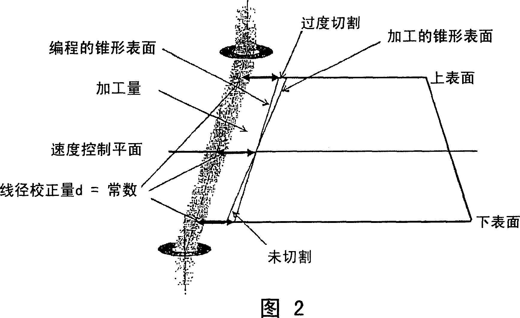
No known publications were found describing techniques to easily solve this problem in tapered machining

Method used


Image

  • Wire electric discharge machine
  • Wire electric discharge machine
  • Wire electric discharge machine

Examples


Embodiment Construction

[0032] First, referring to Fig. 4, the schematic structure and operation of a wire discharge machine to which the present invention can be applied will be described. The basic structure of the wire discharge machine shown is the same as conventional. In particular, reference numeral 1 denotes a workpiece setting table for setting and fixing a workpiece 3 to be processed, having an upwardly facing setting surface 2 that is flat with high precision. In processing, the workpiece 3 is set and fixed on the workpiece setting table with its bottom surface in contact with the setting surface 2 .

[0033] In the workpiece 3 , the entire upper surface (upper surface) 31 is parallel to the bottom surface (lower surface) 32 . Here, a cubic-shaped workpiece 3 is exemplified so that the entire upper surface 31 is parallel to the bottom surface 32 . However, the workpiece 3 can be such that only the upper part is parallel to the bottom surface. Reference numeral 4 denotes a wire electrode...


PUM


Abstract

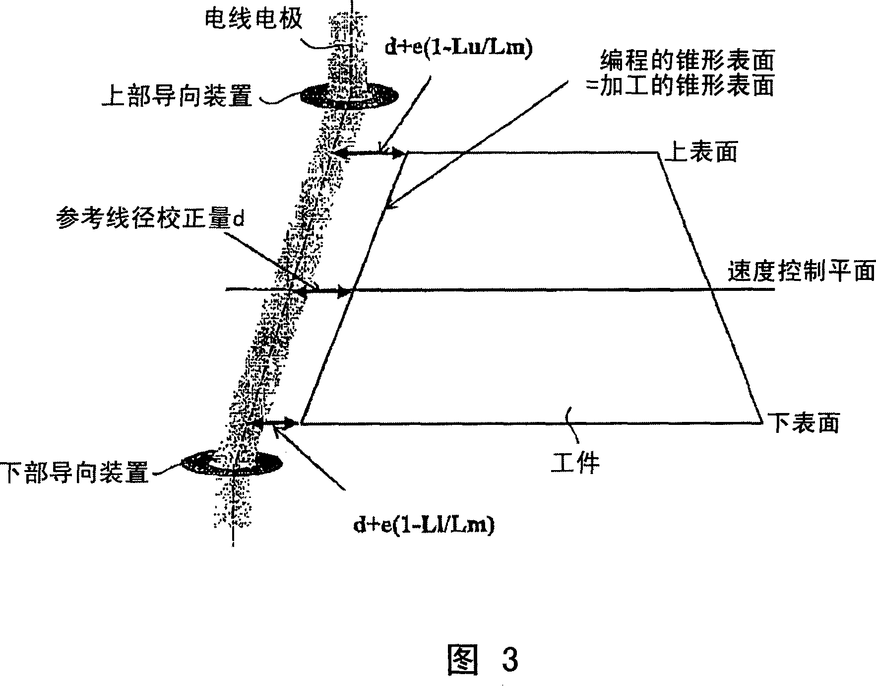
A wire electric discharge machine capable of taper machining with an improved accuracy. A reference wire correction amount d set in advance is determined to be a proper value for a wire-diameter correction amount for a speed control plane, and adjustment amounts for adjusting the reference wire correction amount for the upper and lower surfaces of a workpiece are determined to be proportional to (1-Lu / Lm) and (1-Ll / Lm), respectively, where Lu, Lm and L1 are machining distances at the upper surface, speed control plane and lower surface, respectively. As a proportionality coefficient, a reference adjustment amount e is set in advance. Using adjustment amounts e(1-Lu / Lm) and e(1-Ll / Lm), wire-diameter correction amounts for the workpiece upper and lower surfaces are determined to be d+e(1-Lu / Lm) and d+e(1-Ll / Lm). When a workpiece setting table and upper and lower wire guides are driven, axes are controlled so that a wire electrode follows, on the workpiece upper and lower surfaces, paths shifted by the wire-diameter amounts, respectively.

Description

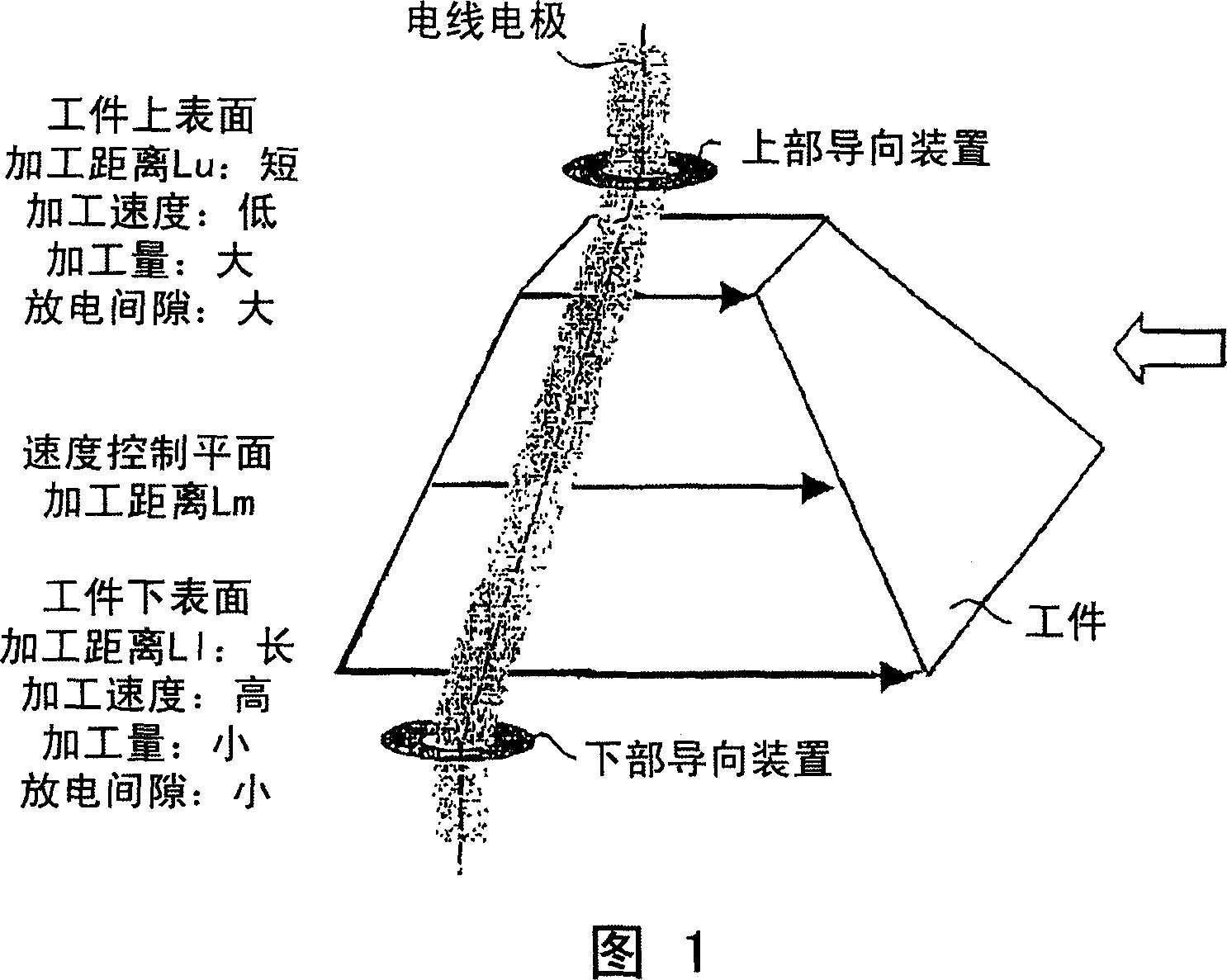
technical field [0001] The present invention relates to a wire discharge machine, in particular to a wire discharge machine with a tapered machining function, which is used for machining workpieces between the first plane and the second plane, so that the machined shape on the first plane is the same as that on the second plane. The processing shape on the plane is different. Background technique [0002] Tapering with wire discharge machines is known. Generally, machining using a wire discharge machine is performed with a workpiece set on an upwardly facing workpiece setting surface. As a result of the tapered machining, the workpiece has inconsistent shapes on the upper and lower surfaces. FIG. 1 schematically shows this conical machining in a cross-section parallel to the direction of the arrows. As can be understood from FIG. 1 , for movement in each block of the machining program, generally, the movement distance (machining distance) Lu of the upper surface of the wo...

Claims


Application Information

Patent Timeline
Patent Type & Authority Applications(China)
IPC IPC(8): B23H9/18B23H1/02B23H7/20
CPCB23H7/065
Inventor 宫岛敬一郎荒川靖雄
Owner FANUC LTD
Learn More