Fan and its frame

A fan frame and fan technology, which is applied in the field of fans with supercharging and diversion effects and their fan frames, can solve the problems of limited volume of the frame body 11, increase of fixed space, shortened life of the fan 1, etc., so as to improve the heat dissipation efficiency, The effect of increasing wind pressure and volume, and increasing wind pressure

Inactive Publication Date: 2007-04-04
DELTA ELECTRONICS INC
View PDF0 Cites 4 Cited by
  • Summary
  • Abstract
  • Description
  • Claims
  • Application Information

AI Technical Summary

Problems solved by technology

However, if the operating efficiency of the fan 1 is improved, additional power costs must be paid, but the temperature inside the fan 1 will inevitably increase accordingly, resulting in a shortened life of the fan 1
Furthermore, in order to increase the volume of the impeller 20, its precondition is that the volume of the frame body 11 must be increased to accommodate the impeller 20. However, the volume of the frame body 11 is often limited by the limited fixed space in the casing of the electronic components. cannot be increased arbitrarily

Method used


Image

  • Fan and its frame
  • Fan and its frame
  • Fan and its frame

Examples


Embodiment Construction

[0021] A fan and its fan frame according to a preferred embodiment of the present invention will be described below with reference to related drawings.

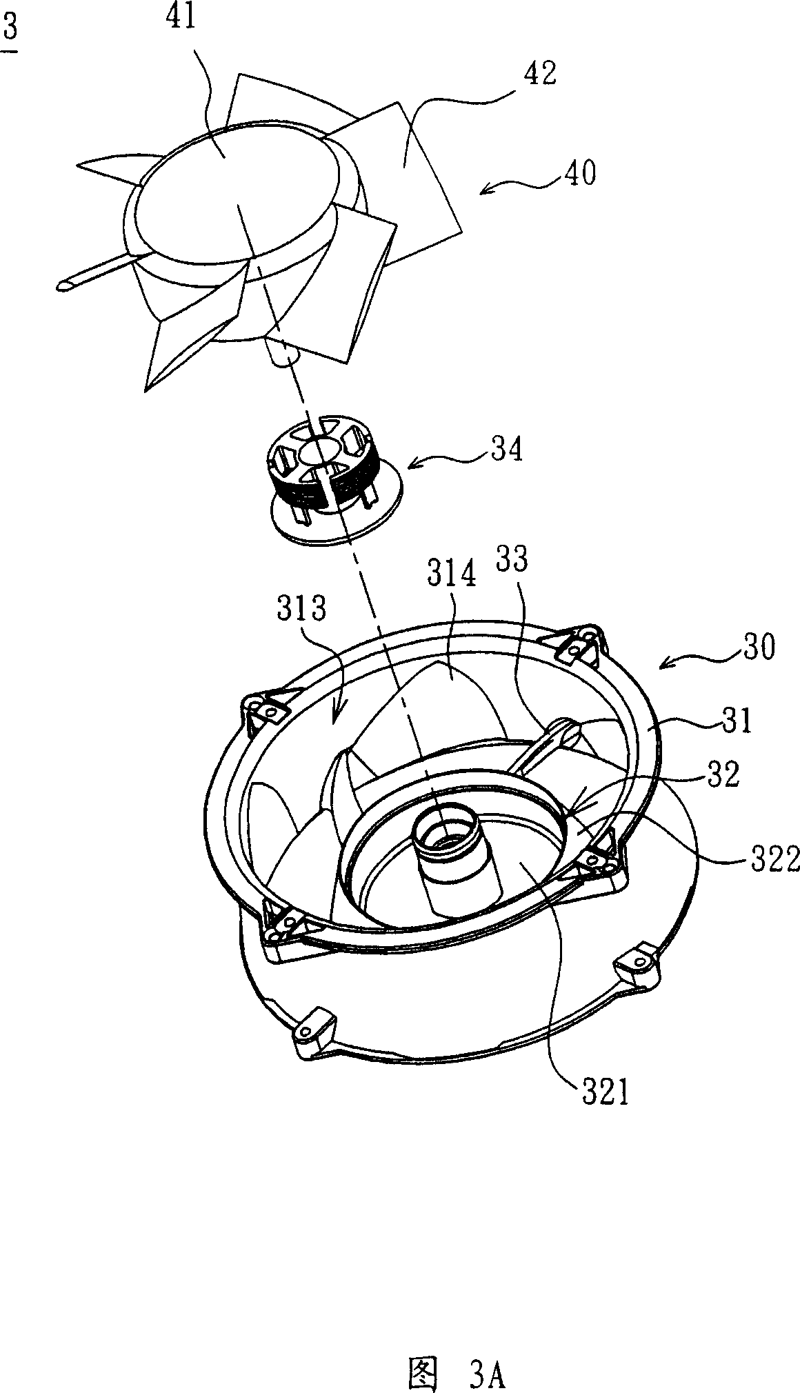
[0022] Please refer to Figure 3A, Figure 3B and Figure 4, Figure 3A is an exploded view of a fan in a preferred embodiment of the present invention, Figure 3B is a cross-sectional view of the fan in Figure 3A, and Figure 4 is a fan frame in Figure 3A schematic diagram. The fan 3 includes a frame 30 , an impeller 40 and a driver 34 . Wherein, the fan frame 30 has a frame body 31 , a base 32 and at least one support member 33 , and the number of the support members 33 is not limited. Here, five support members 33 are taken as an example.

[0023] The base 32 is arranged in the frame body 31, and the base 32 has a bottom 321 and a pressurized part 322, the pressurized part 322 is arranged around the periphery of the bottom 321, and a shaft tube part extends vertically from the center of the base 32, which can be used for the im...


PUM


Abstract

There is disposed a fan, which includes a fan frame and an impeller. The fan frame has a frame body, a base and at least one support member. There is at least a deflector part on the inside wall of the frame body. The base is disposed in the frame body and has a bottom part and a supercharging part set on the periphery of the bottom. The support member is set between the frame body and the supercharging part of the base and the impeller is disposed in the frame body and is supported by the base.

Description

technical field [0001] The invention relates to a fan and its fan frame, in particular to a fan and its fan frame with pressurization and flow guiding effects. Background technique [0002] In order to prevent the general electronic components from being polluted by dust in the atmosphere, most of the electronic components (such as the central processing unit) are arranged in a housing, but since the electronic components will generate heat energy when they are in operation, if the heat energy is not dissipated, it will lead to electronic The stability and performance of the components will drop, and even the electronic components may be burned. Therefore, fans are usually used to keep the electronic components within a certain operating temperature range to maintain normal operation. [0003] Please refer to FIG. 1 and FIG. 2 , FIG. 1 is an exploded view of a conventional fan, and FIG. 2 is a cross-sectional view of the fan in FIG. 1 . A conventional fan 1 includes a fan f...

Claims


Application Information

Patent Timeline
Patent Type & Authority Applications(China)
IPC IPC(8): F04D29/52F04D29/54F04D25/08
Inventor 篮重凯陈弘琪庄德财黄文喜
Owner DELTA ELECTRONICS INC
Why Eureka
Try Eureka