
Planar display device

A flat-panel display and display surface technology, applied to instruments, instrument parts, support structures on hinges/pivots, etc., can solve the problem that the flat-panel display cannot be rotated in multiple directions

Inactive Publication Date: 2007-04-04
INNOCOM TECH SHENZHEN +1
View PDF0 Cites 4 Cited by
  • Summary
  • Abstract
  • Description
  • Claims
  • Application Information

AI Technical Summary

Problems solved by technology

[0005] In order to overcome the defect that the prior art flat display cannot be rotated in multiple directions, it is necessary to provide a flat display capable of rotating in multiple directions

Method used


Image

  • Planar display device
  • Planar display device
  • Planar display device

Examples


Embodiment Construction

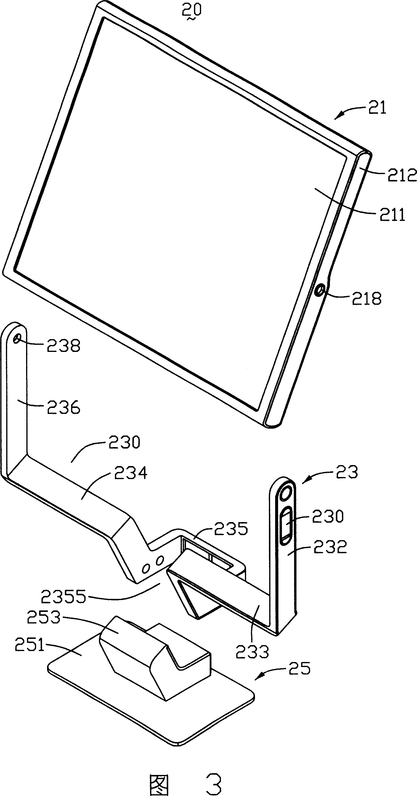
[0018] Please refer to FIG. 3 and FIG. 4 , FIG. 3 is an exploded view of the flat-panel display disclosed in the first embodiment, and FIG. 4 is a rear view of the flat-panel display. The flat panel display 20 includes a display panel 21, a support structure 23 and a base 25, one end of the support structure 23 is connected to the display panel 21 and supports the display panel 21, the other end of the support structure 23 is connected to the base 25, Used to hold the support structure 23 .

[0019] The display panel 21 includes a display surface 211, a back surface 210 opposite to the display surface 211, and two opposite sides 212, 216 adjacent to the display surface 211, the two sides 212, 216 are substantially perpendicular to the base 25, The back side 210 can be divided into an upper half and a lower half with the center line as a boundary, and the lower half is mirror-finished to form a mirror 215, and two symmetrical pivots 218 are respectively arranged on the two side...


PUM


Abstract

The flat panel display comprises a display panel, a pivot and a supporting structure used for supporting the display panel. The display panel comprises a display surface, a reverse side corresponding to the display panel and a lateral side adjacent to the display surface; the supporting structure is attached to the lateral side of the display panel through the pivot, and the display panel can make rotation around the supporting structure by using the pivot as the center.

Description

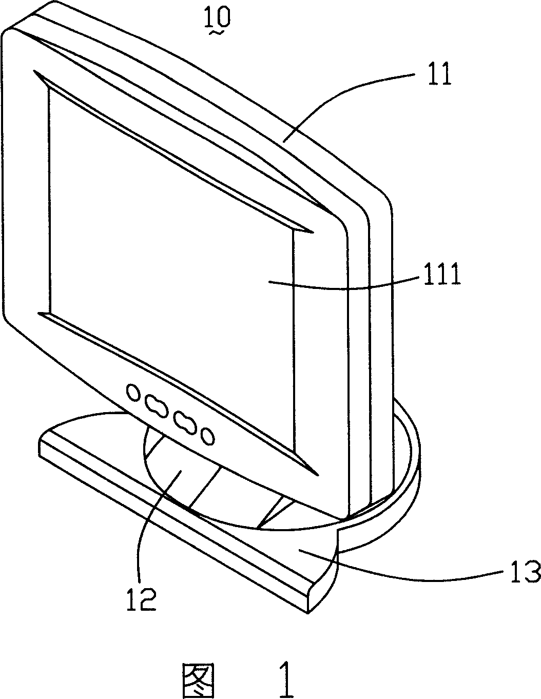
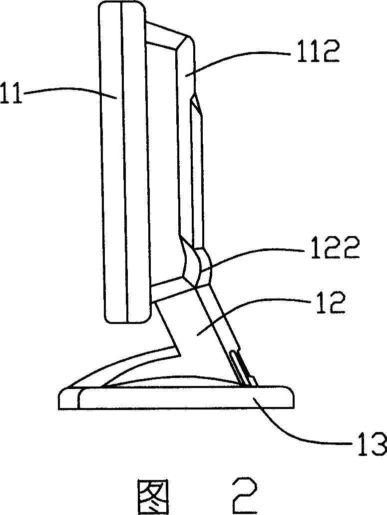
【Technical field】 [0001] The invention relates to a rotatable flat display. 【Background technique】 [0002] In today's era of rapid technological development, desktop computers have become an indispensable part of modern people's daily life. Generally speaking, a desktop computer includes at least a computer host and a display, and the display includes a cathode ray tube (Cathode Ray Tube, CRT) display and a liquid crystal display. Among them, since the liquid crystal display has advantages such as thinness, shortness, no radiation, and soft picture that the cathode ray tube display does not have, the liquid crystal display has a tendency to gradually replace the cathode ray tube display. [0003] Please refer to FIG. 1 and FIG. 2 , which are schematic diagrams of a liquid crystal display in the prior art. The liquid crystal display 10 includes a panel 11 , a stand 12 and a base 13 . The panel 11 includes a display surface 111 and a back surface 112 opposite to the displa...

Claims


Application Information

Patent Timeline
Patent Type & Authority Applications(China)
IPC IPC(8): H05K7/18H05K7/16G12B9/08G09F9/00
Inventor 陈永祥黄泽民蔡孟泽黄明智吕鑫
Owner INNOCOM TECH SHENZHEN
Learn More