

Electronic component moving device, surface mounting machine and ic automatically conveying device
A technology for electronic components and transfer devices, which is applied to electrical components, electrical components, printed circuits, etc., can solve the problem of not being able to load multiple inspection sockets at the same time for component inspection, and achieve the effect of correcting adsorption deviation and correcting deviation.
- Summary
- Abstract
- Description
- Claims
- Application Information
AI Technical Summary
Problems solved by technology
Method used
Image

Examples
no. 1 Embodiment
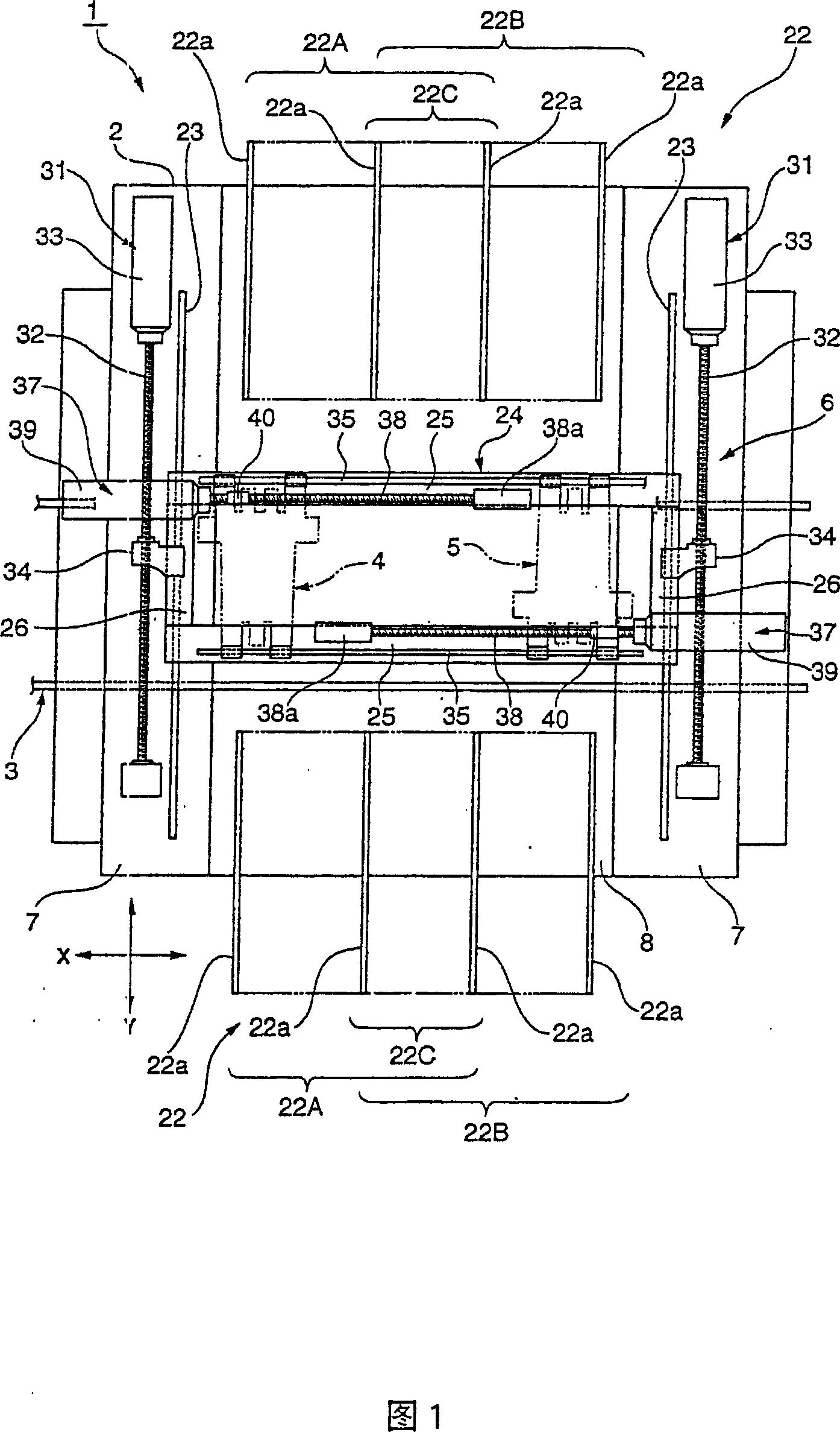
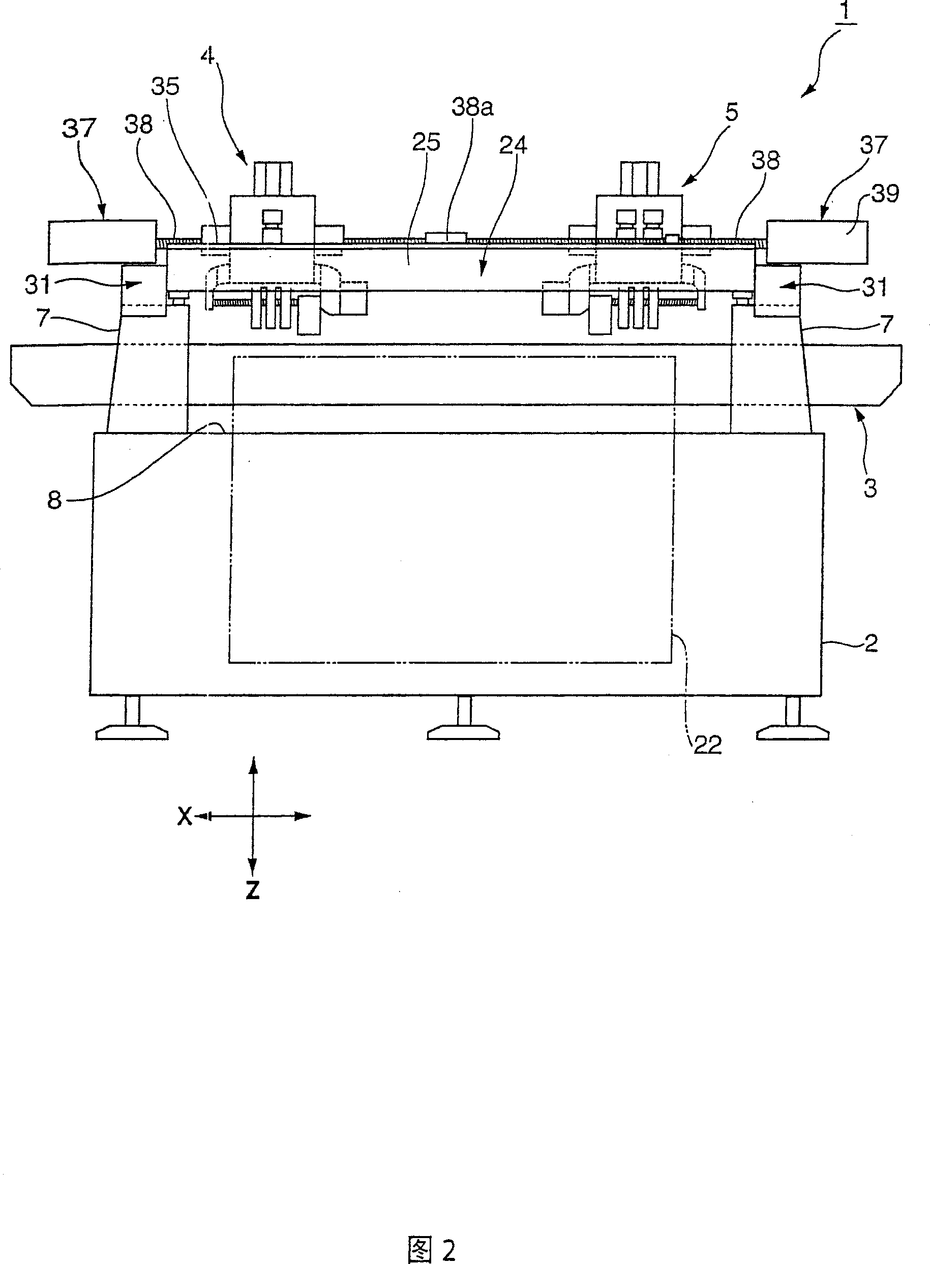
[0087] Hereinafter, an embodiment of an electronic component transfer device according to the present invention will be described in detail with reference to FIGS. 1 to 16 . Here, an example in which the electronic component transfer device according to the present invention is applied to a surface mounter will be described.
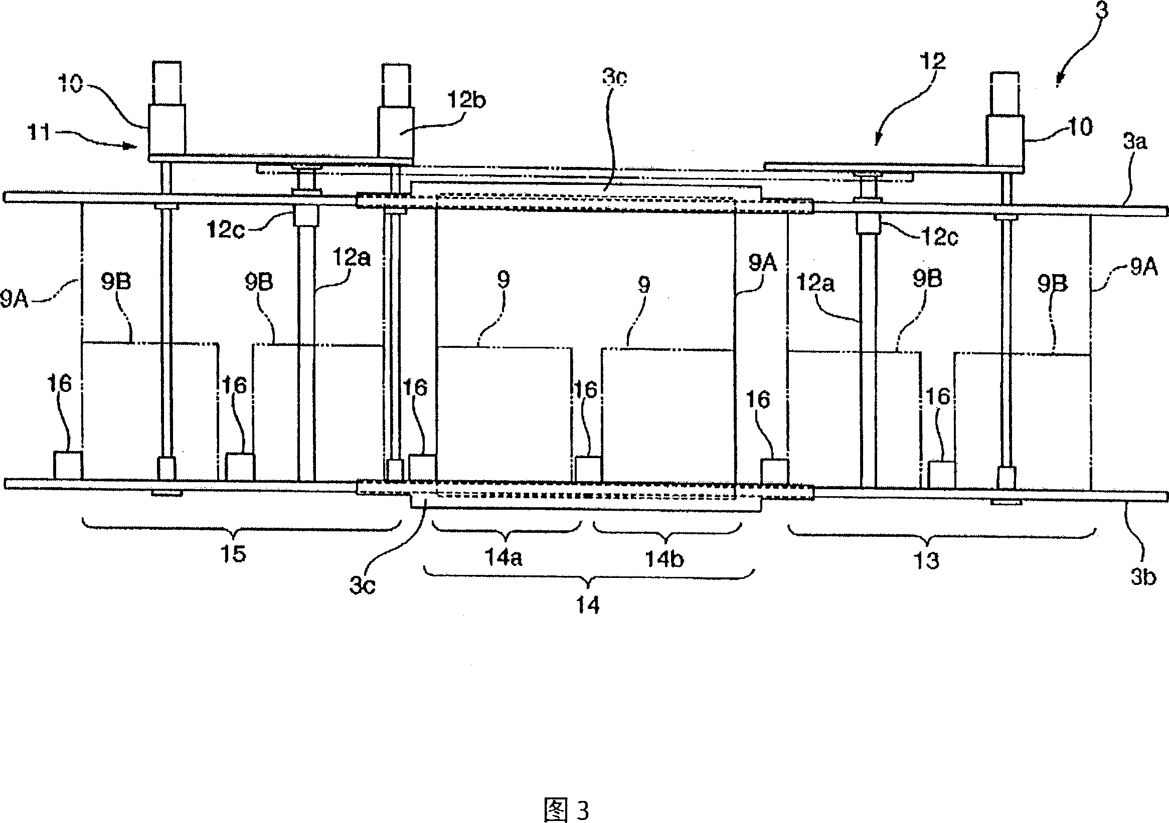
[0088] Fig. 1 is a top view showing the structure of the surface mounter of this embodiment, Fig. 2 is the same side view, Fig. 3 is a top view showing the structure of the conveyor belt, Fig. 4 is a top view showing the structure of the suction head unit, Fig. 5 is a top view of the suction head unit side view. 6 to 8 are sectional views showing the structure of the third driving device. FIG. 6 is a sectional view taken along line VI-VI in FIG. 5 , and FIG. 7 is a sectional view taken along line VII-VII in FIG. 5 . Cutaway view along line VIII.
[0089] Fig. 9 is a longitudinal sectional view of the suction head, which is a sectional view taken along ...
no. 2 Embodiment
[0193] The electronic component transfer device according to the present invention can be applied to an automatic IC transfer device as shown in FIG. 21 .
[0194]21 is a plan view showing the configuration of an automatic IC transfer device using the electronic component transfer device according to the present invention. In this figure, components that are the same as or correspond to the structures described above with respect to FIGS. 1 to 12 are denoted by the same reference numerals, and detailed description thereof will be appropriately omitted.
[0195] The IC automatic transfer device 210 shown in FIG. 21 includes: a plurality of inspection sockets 212 arranged on one end of the base 211 (the end in the Y direction in FIG. 21 ), and four tray lifters arranged on the base 211. Table 213 , component recognition camera 214 installed between lift table 213 and inspection socket 212 , moving device 215 for moving suction head unit 4 horizontally above base 211 , and the li...
PUM
 Abstract
Description
Claims
Application Information