
Optoelectronic module

一种光电模块、光学的技术,应用在电视、电气元件、彩色电视等方向,能够解决不可使用、限制成像模块处理温度等问题,达到便于维修性、廉价制造、容易替换的效果

Inactive Publication Date: 2011-04-20
ROBERT BOSCH GMBH
View PDF0 Cites 0 Cited by
  • Summary
  • Abstract
  • Description
  • Claims
  • Application Information

AI Technical Summary

Problems solved by technology

However, the processing temperature of the imaging module is limited in this way, so that the known inexpensive soldering processes for fastening such imaging modules to carrier elements, for example, carrying the electronic and optical components, cannot be used

Method used


Image

  • Optoelectronic module
  • Optoelectronic module
  • Optoelectronic module

Examples


Embodiment Construction

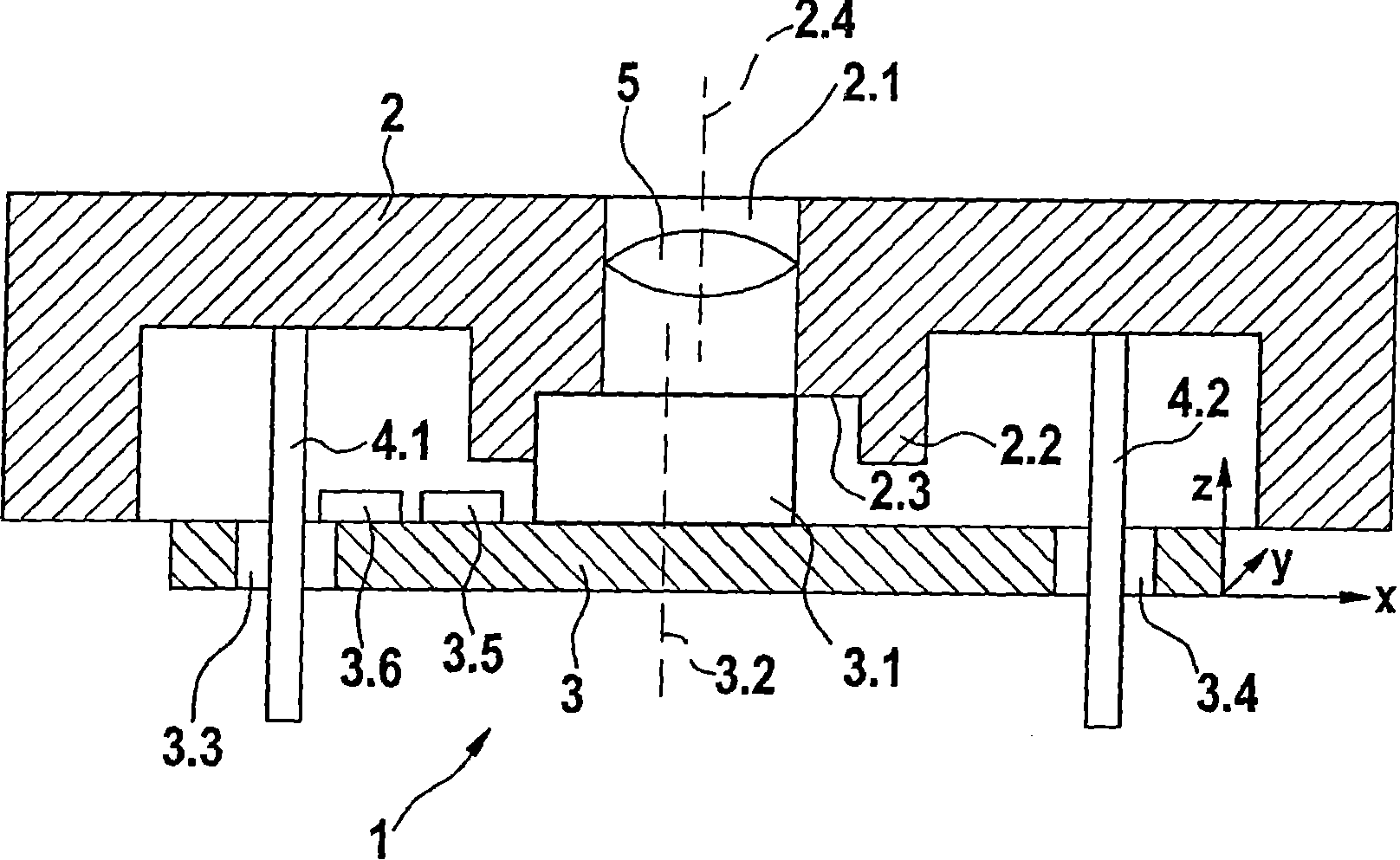
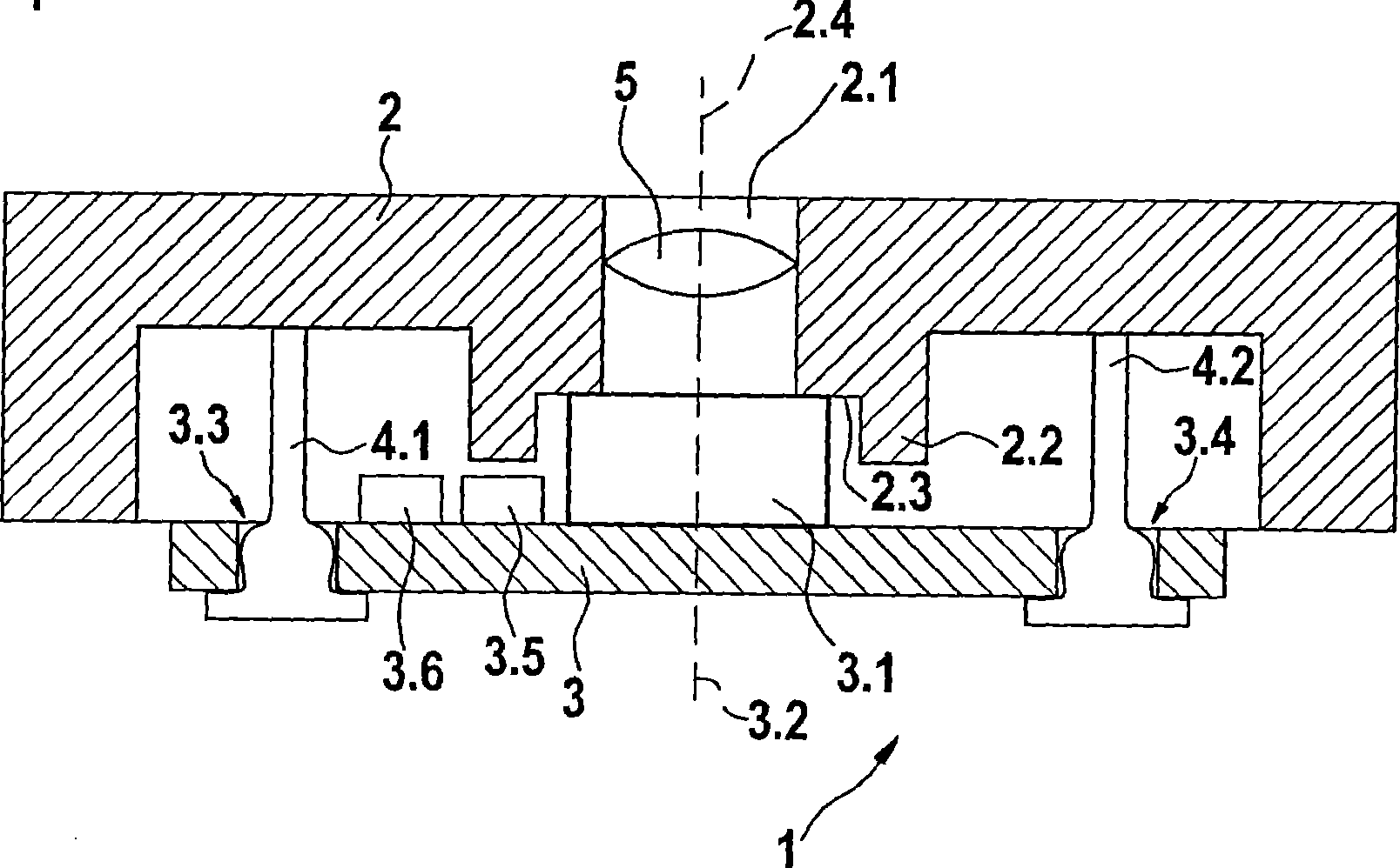
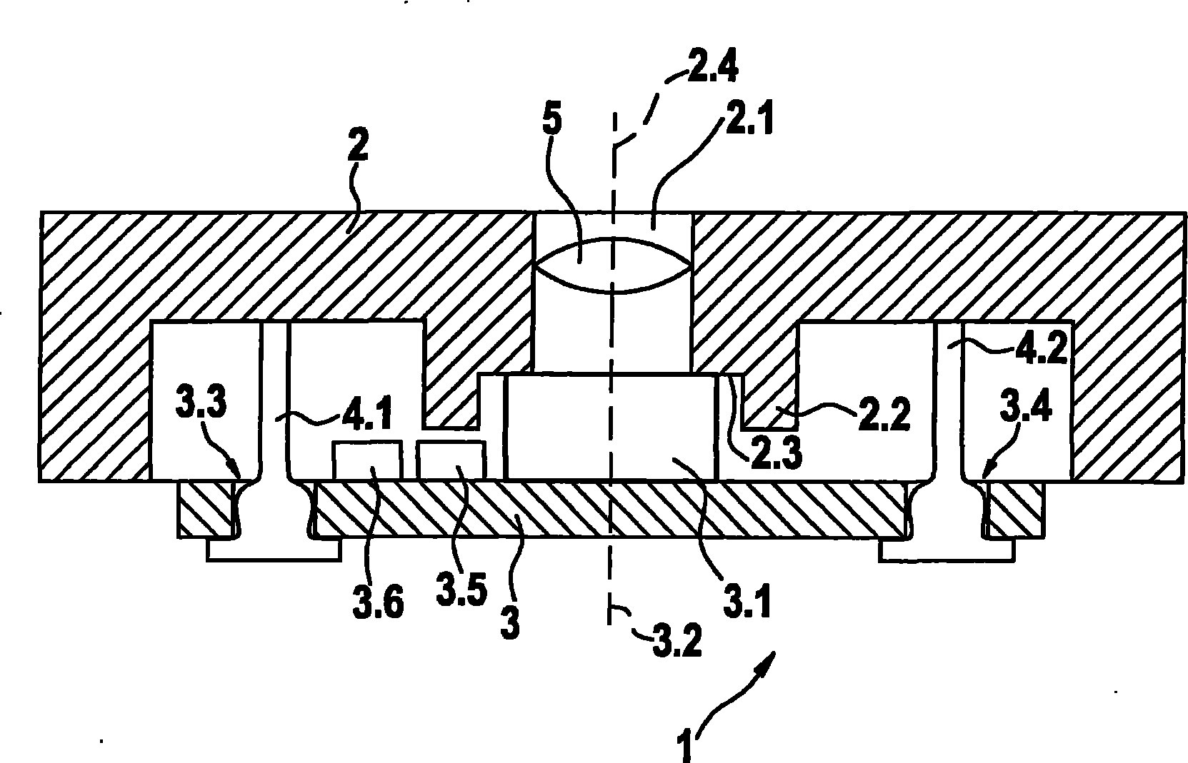
[0019] The invention relates to an optoelectronic module having a housing and a carrier element arranged in the housing for optical and electronic components. At least one optical element is arranged both in the housing and on the carrier element. The carrier element is connected to the housing via a fastening device. Expediently, after the mounting of the carrier element, the fastening device is upset in such a way that the material of the fastening device fills the recesses provided in the carrier element and thus fixes the carrier element.

[0020] figure 1 A schematic illustration of a photovoltaic module 1 in a first production stage is shown in cross section. The optoelectronic module 1 comprises a housing 2 for receiving a carrier element 3 . An optical channel 2.1 is arranged in the housing 2. An optical element 5 is fixed in this optical channel 2.1, the optical axis of which is marked with 2.4. The optical channel 2.1 opens into a bearing surface 2.3, which is d...


PUM


Abstract

The invention relates to an optoelectronic module (1) comprising a housing (2) and a support element (3) for optical and electronic components, which is disposed in said housing (2). At least one optical component (3.1, 5) is arranged both in the housing (2) and on the support element (3). The support element (3) is joined to the housing (2) with the aid of fastening means (4.1, 4.2). The fastening means (4.1, 4.2) are appropriately compressed after assembling the support element such that the material of the fastening means (4.1, 4.2) fills recesses (3.3, 3.4) located in the support element (3) and thereby fixes the support element.

Description

technical field [0001] The invention relates to an optoelectronic module having a housing and a carrier element arranged in the housing for optical and electronic components. Background technique [0002] In the automotive industry, video cameras with optical sensors mounted on the vehicle are increasingly being used in order to enable an optical detection of the surroundings of the vehicle. The high requirements placed on the alignment of the imaging optics relative to the light-sensitive sensor often lead to the use of so-called imaging modules, in which the imaging optics are attached directly to the light-sensitive sensor. However, the processing temperature of the imaging module is limited in this way, so that the known inexpensive soldering processes for fastening such imaging modules to a carrier element, for example carrying the electronic and optical components, cannot be used. Contents of the invention [0003] According to the invention, an optoelectronic modul...

Claims


Application Information

Patent Timeline
Patent Type & Authority Patents(China)
IPC IPC(8): H04N5/225H04N25/00
CPCH04N5/2252H04N5/2251H04N5/2254H04N23/51H04N23/55
Inventor 罗兰·施密德延斯·希克
Owner ROBERT BOSCH GMBH
Learn More