Working machine

A technology of working machinery and engine, which is applied in the field of roofing working machinery, can solve the problems of increased burden on the operator, higher unit price of the lock, and shielding the cab, etc., and achieves the effect of improving workability and reducing costs

Inactive Publication Date: 2007-04-11
NIHON KENKI CO LTD
View PDF1 Cites 3 Cited by
  • Summary
  • Abstract
  • Description
  • Claims
  • Application Information

AI Technical Summary

Problems solved by technology

[0006] Therefore, before changing the hood from the closed state to the open state, the so-called cumbersome work (operation) that requires the operator to appropriately change the working posture while using both hands cannot reduce the burden on the operator.
[0007] Moreover, in construction machinery such as hydraulic excavators, the upper position of the roof is at a height above 2 to 3 m (meters) from the ground, so when the operator opens and closes the engine cover on the roof, he sometimes needs to pass through a narrow In order not to accidentally fall from a high position on the roof, the operator must be careful enough, so there is a problem of increasing the burden on the operator.
[0008] In addition, since the latch as the closing limiter used in the prior art is composed of multiple parts such as the hook and the clamp shaft as described above, the structure is complicated, and the unit price of each latch becomes high. In addition, the workability of assembling the latch between the engine cover and the roof is also poor.
[0009] Furthermore, the latch used in the prior art is installed in the height direction of the engine cover, and it is necessary to make the height dimension of the engine cover larger than the entire length of the latch.
However, if the height dimension of the engine cover is increased, there is a problem that the rear view of the cab is blocked and a wide view cannot be ensured.

Method used


Image

  • Working machine
  • Working machine
  • Working machine

Examples


Embodiment Construction

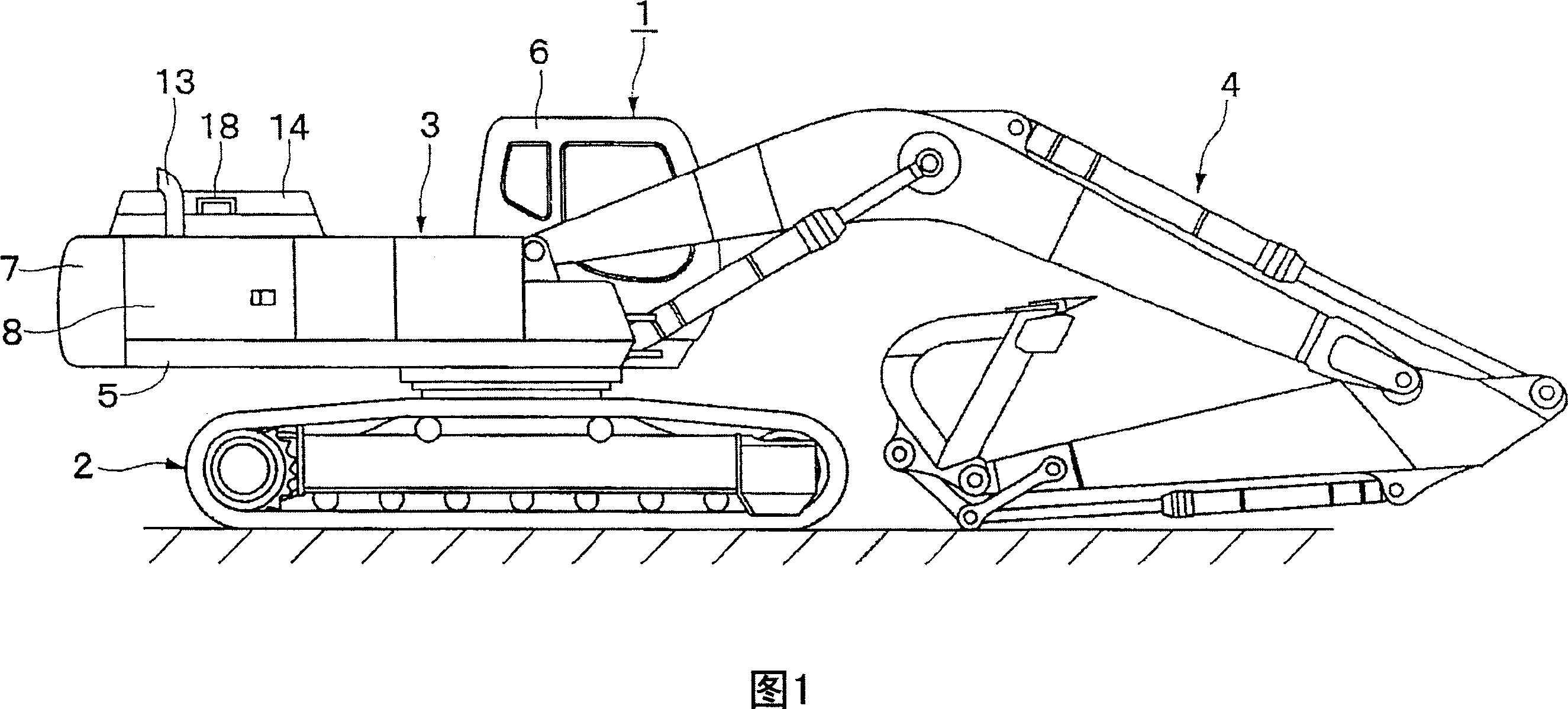
[0032] Hereinafter, a case in which the working machine according to the embodiment of the present invention is applied to a hydraulic excavator will be described in detail with reference to the drawings.

[0033] Here, FIGS. 1 to 8 show a first embodiment of the present invention. In the figure, reference numeral 1 is a hydraulic excavator as a working machine. The general structure of the hydraulic excavator 1 includes: a crawler-type undercarriage 2 capable of self-propelling as shown in FIG. 1 ; 2 on the upper rotating body 3; and, in order to carry out excavation operations such as sandy soil, etc., the working device 4 is vertically movably arranged on the front portion of the upper rotating body 3.

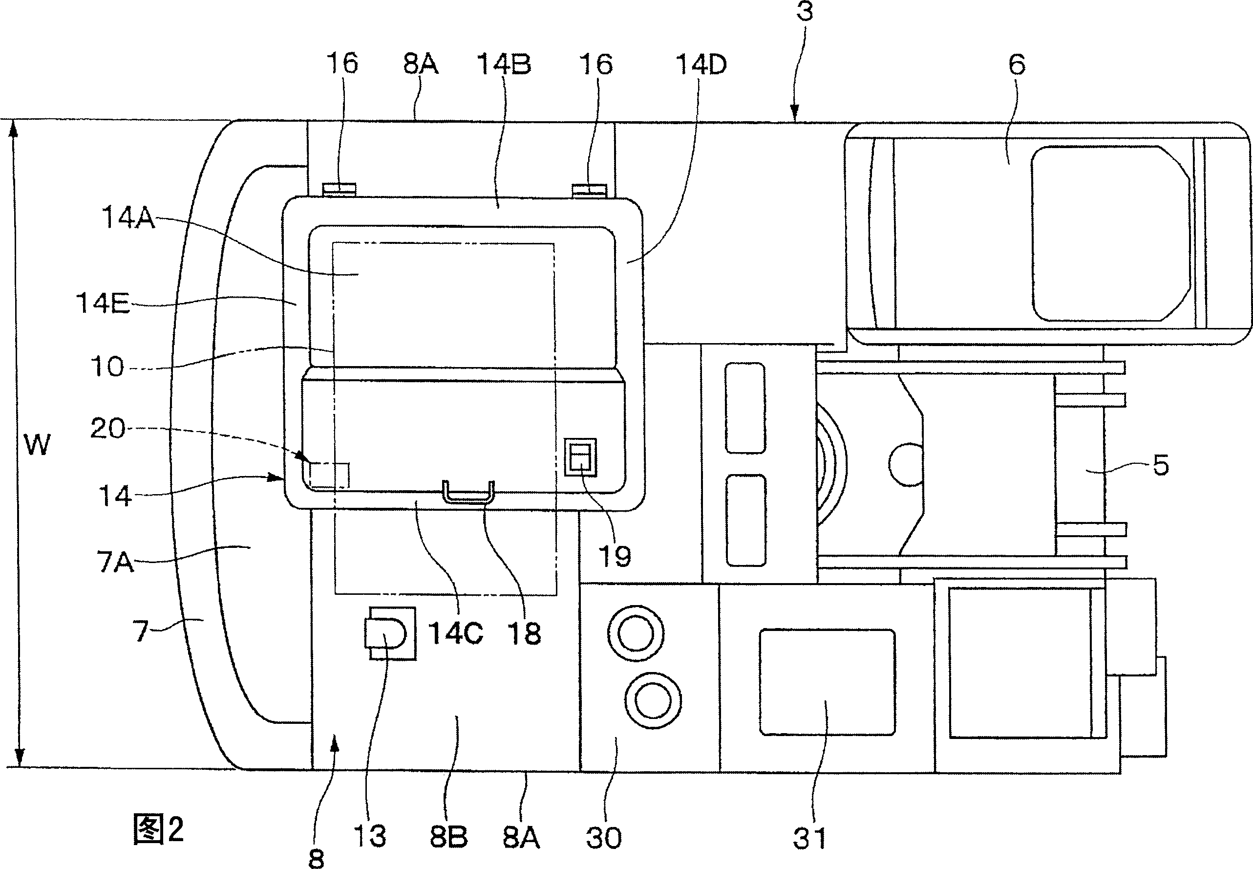
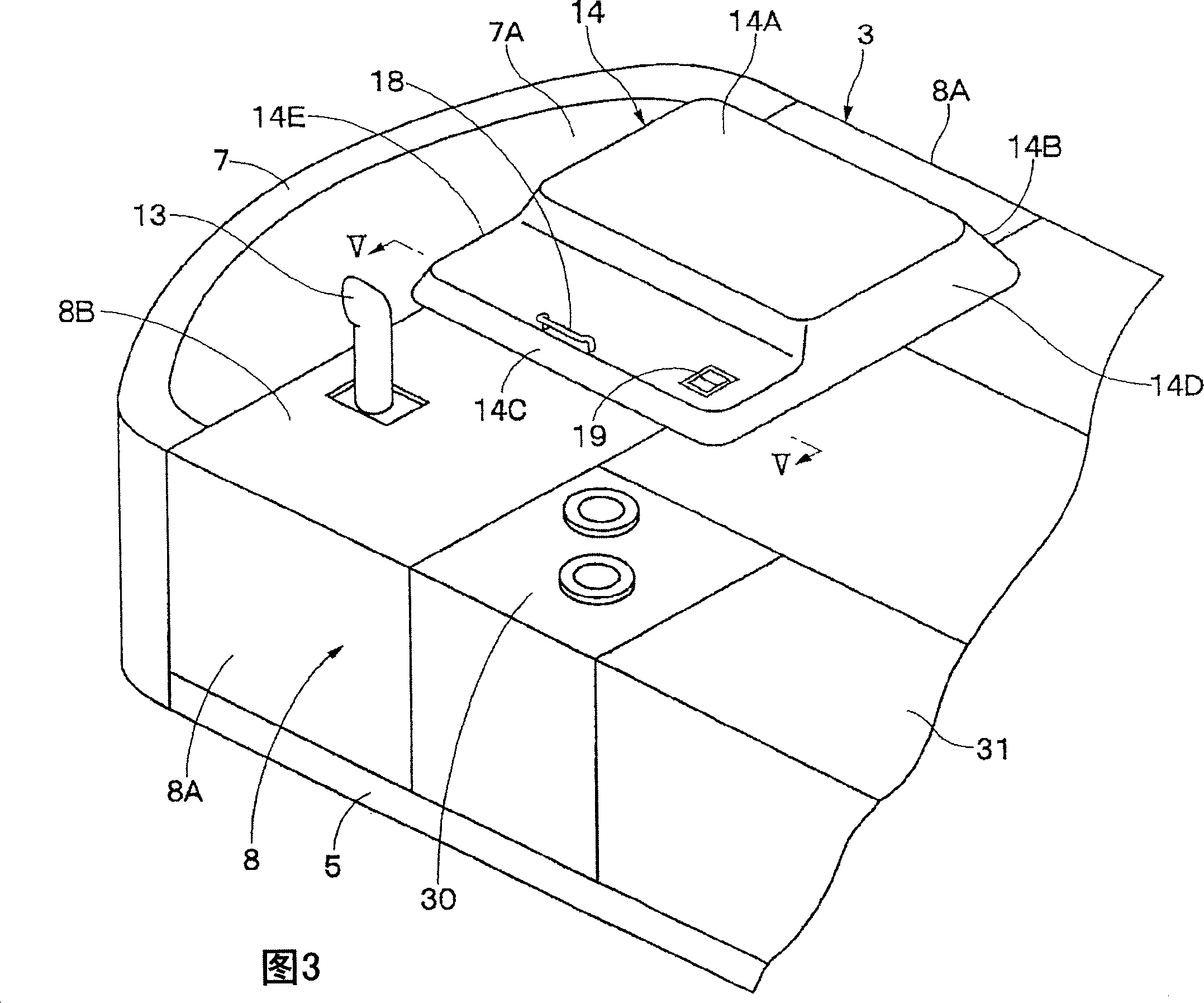
[0034] In this case, the upper turning body 3 of the hydraulic excavator 1 together with the lower traveling body 2 constitutes a vehicle body of the working machine. Further, the upper turning body 3 is constituted by a turning frame 5 , a cab 6 , a counterweight 7 , a ro...


PUM


Abstract

A working machine which enables an engine cover to be easily operated for opening/closing with only one hand by simplifying a structure of a cover-closing stopper, and can reduce a burden on an operator. The cover-closing stopper (20) for keeping the engine cover (14) in a closed state comprises a stopper retainer (21) which is fixed to a support (8D) of a building cover (8) via a supporting member (24) etc., and a stopper member (27) which is provided on the reinforcing plate (14G) of the engine cover (14) via a bracket (25). When the engine cover (14) is put into an opened state from a closed state, the whole of the engine cover (14) is deflection-deformed by an external force for lifting the handle (18) of the engine cover (14) in a cover opening direction. The utilization of the deflection deformation of the engine cover (14) makes the stopper member (27) of the cover-closing stopper (20) shifted in the direction of being separated from a latching part (21B) of the stopper retainer (21), so that they can be unlatched from each other.

Description

technical field [0001] The present invention relates to a work machine suitable for use as a construction machine such as a hydraulic excavator, a crane, a wheel loader, a forklift, or a transportation machine, and more particularly to a work machine provided with a roof for accommodating a power source such as an engine. Background technique [0002] In general, working machines (construction machines) such as hydraulic excavators have a structure in which a roof is provided on the frame of the vehicle body, and a machine room that accommodates a power source such as an engine is formed inside by the roof. In addition, the structure adopted is: an opening for inspection of the engine in the maintenance and inspection machine room is provided on the roof top, and the opening is covered by an engine cover (engine cover) in a switchable manner (for example, refer to Patent Document 1-Specific Publication No. 2001-323507). [0003] In addition, between the above-mentioned engi...

Claims


Application Information

Patent Timeline
Patent Type & Authority Applications(China)
IPC IPC(8): E02F9/00
CPCB60Y2200/15B60Y2200/412B60Y2200/415B60Y2200/416E02F9/0858E02F9/0891
Inventor 津久井洋山田康裕
Owner NIHON KENKI CO LTD
Why Eureka
Try Eureka