Footwear sole with forefoot stabilizer, ribbed shank, and layered heel cushioning

一种鞋芯垫片、脚后跟的技术,应用在组件的鞋底领域

Active Publication Date: 2007-04-18
ARET INT CORP
View PDF0 Cites 22 Cited by
  • Summary
  • Abstract
  • Description
  • Claims
  • Application Information

AI Technical Summary

Problems solved by technology

Lower heel pad positioned in the heel area

Method used


Image

  • Footwear sole with forefoot stabilizer, ribbed shank, and layered heel cushioning
  • Footwear sole with forefoot stabilizer, ribbed shank, and layered heel cushioning
  • Footwear sole with forefoot stabilizer, ribbed shank, and layered heel cushioning

Examples


Embodiment Construction

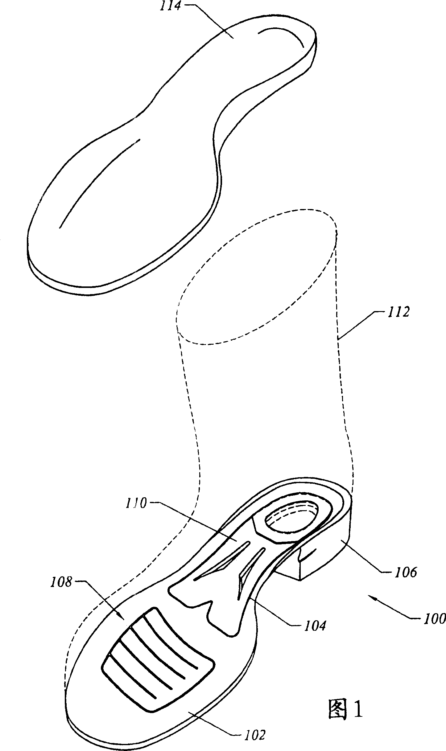
[0015] FIG. 1 is a perspective view of a shoe bottom 100 configured in accordance with one embodiment of the present invention. The sole bottom 100 includes a forefoot region 102 , a midfoot region 104 and a heel 106 . Forefoot stabilizer 108 is positioned in forefoot region 102 . A shank 110 is positioned in the midfoot region 104 . The sole bottom 100 may be used in conjunction with any type of upper shoe structure 112 including boots, shoes, and the like. FIG. 1 also illustrates an insole 114 that may be used in accordance with embodiments of the present invention.

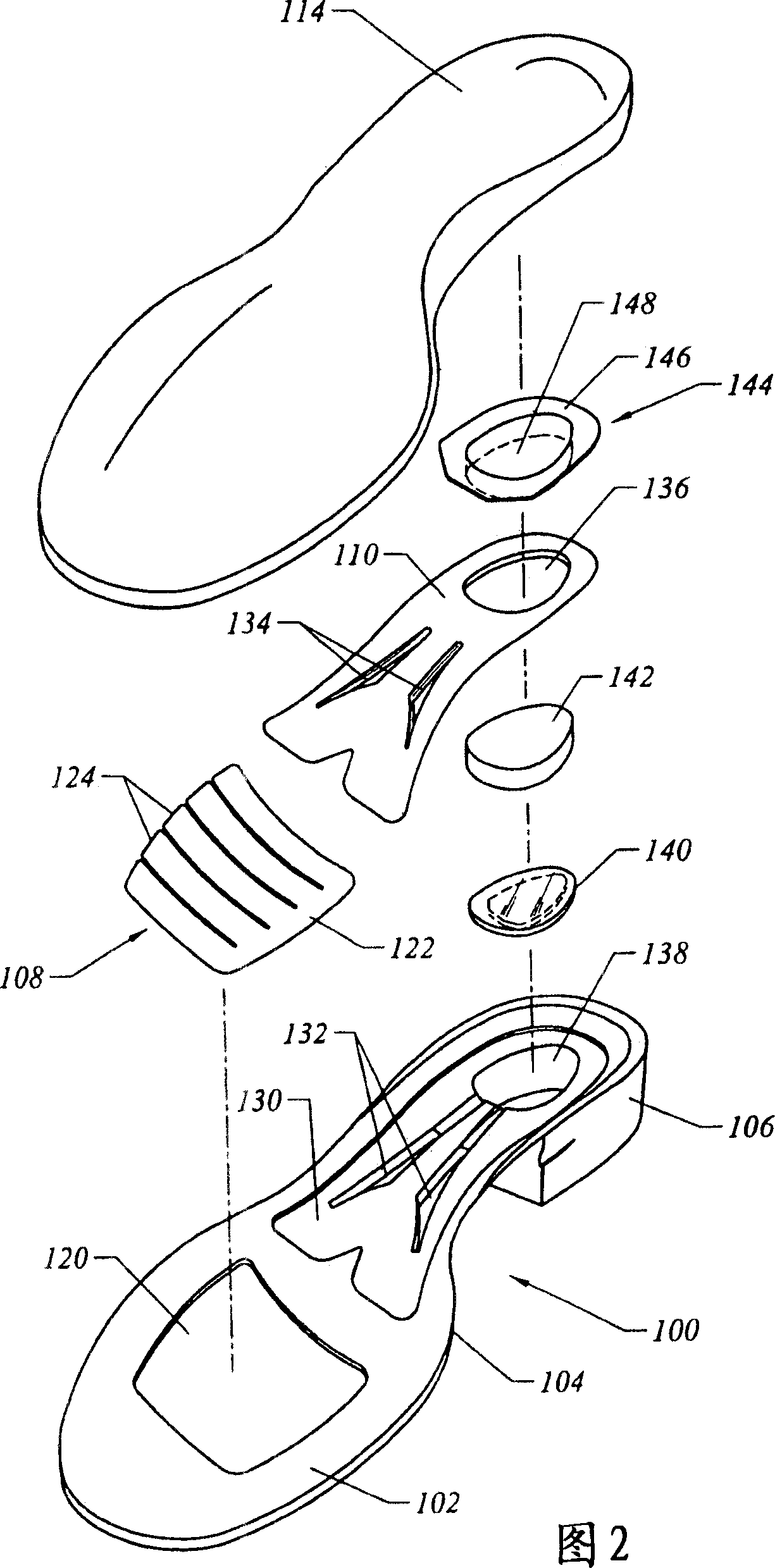
[0016] Fig. 2 is an exploded view of the sole of the present invention. Figure 2 illustrates a sole bottom 100, which may be formed from an injection molded solid rubber compound. The sole bottom 100 has a forefoot stabilizer receptacle 120 positioned in the forefoot region 102 . The forefoot stabilizer receptacle 120 is configured to receive the forefoot stabilizer 108 . The forefoot stabilizer 108 inclu...


PUM


Abstract

A footwear sole includes a footwear sole base with a forefoot region, a mid-foot region, and a heel region. A lower heel cushion is positioned in the heel region. An upper heel cushion is positioned over the lower heel cushion. A shank with reinforcement ribs is positioned in the mid-foot region. A forefoot stabilizer is positioned in the forefoot region. The forefoot stabilizer includes an axial spine and lateral ribs to facilitate forward movement and lateral support. The footwear sole may be used in combination with a foot bed with a flexible base and a rigid orthotic structure. The foot bed may include elastomer cushioning domes at heel and metatarsal impact points. The foot bed may include a liner with moisture wicking and anti-mic.

Description

technical field [0001] The present invention generally relates to footwear. More specifically, the present invention relates to shoe soles with components that promote shock absorption, foot stability, and natural gait. Background technique [0002] Various efforts have been made to improve the properties of shoe soles. These efforts have only addressed a single problem, such as shock absorption in the heel area. Unfortunately, even focusing on a single problem only yields a second-best design to solve them. Furthermore, a design resulting from a focus on solving a single problem constitutes a stack of discrete components or stacks. These designs are not integrated and operate in an orderly manner to improve the performance of the sole. [0003] In view of the foregoing, it would be desirable to provide an improved shoe sole. In particular, it is desirable to provide a sole that optimally addresses individual concerns, such as shock absorption and foot stability, while ...

Claims


Application Information

Patent Timeline
Patent Type & Authority Applications(China)
IPC IPC(8): A43B13/18A43B21/02A43B21/36A43B7/00
CPCA43B21/26A43B7/144A43B23/22A43B7/1445A43B1/0072A43B13/141
Inventor C·费勒M·麦卡伦
Owner ARET INT CORP
Why Eureka
Try Eureka