Milling cutter, especially a round-head milling cutter

a milling cutter and cutter head technology, applied in the field of milling cutters, can solve the problems of exposing the tool to stress, the cutting edge cannot withstand greater load, and the machining quality becomes critical, and achieves the effect of long service life and high quality

Active Publication Date: 2013-02-28
KENNAMETAL INC
View PDF13 Cites 15 Cited by
  • Summary
  • Abstract
  • Description
  • Claims
  • Application Information

AI Technical Summary

Benefits of technology

[0009]Proceeding from this, the invention is based on the object of specifying a milling cutter, in particular a round-he...

Problems solved by technology

In any case, fundamentally, there is the problem that the machining quality becomes critical as the process speed increases, or that the cutting edges do not withstand be...

Method used


Image

  • Milling cutter, especially a round-head milling cutter
  • Milling cutter, especially a round-head milling cutter
  • Milling cutter, especially a round-head milling cutter

Examples


Embodiment Construction

[0038]In the figures, parts that perform the same function are denoted by the same references.

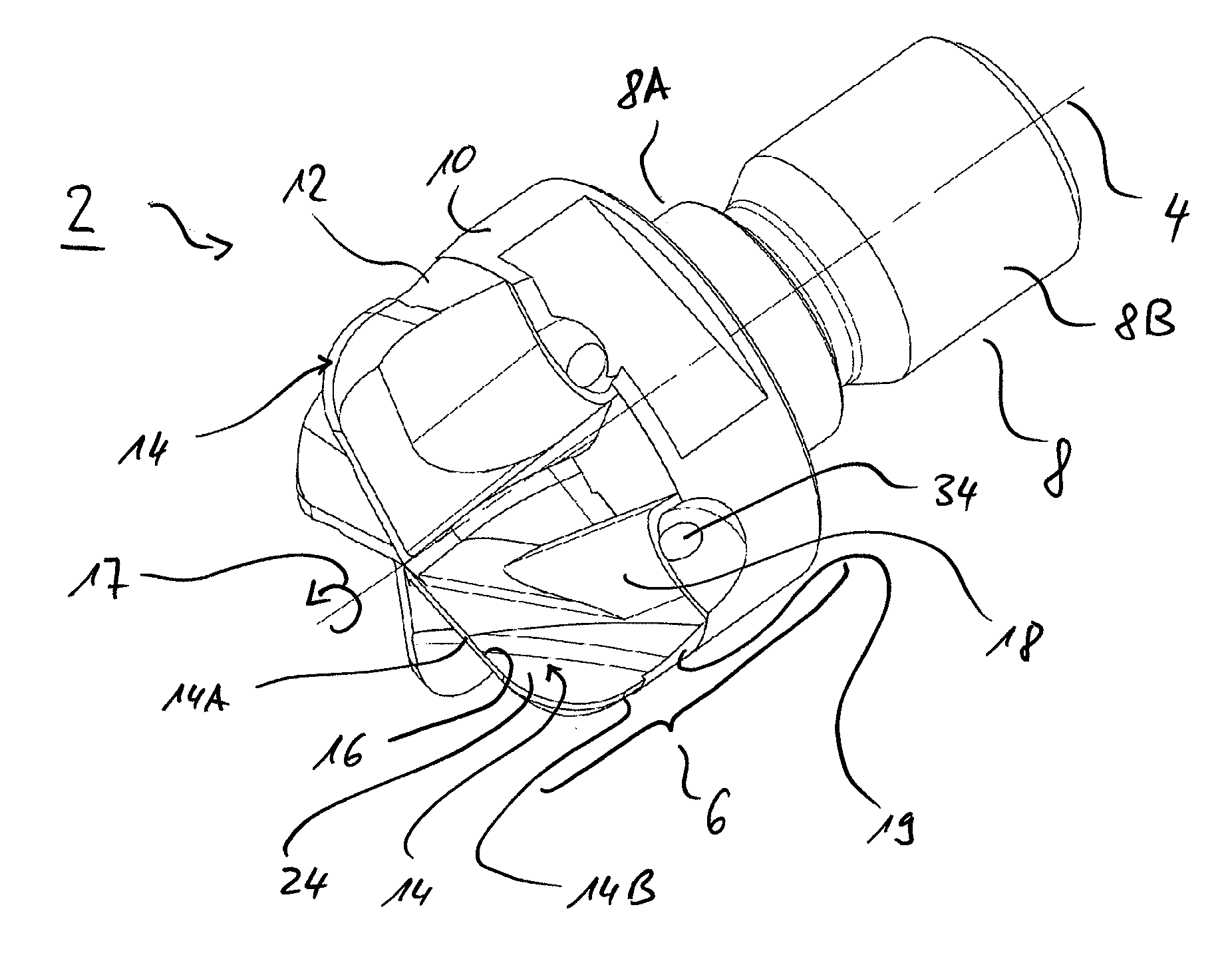
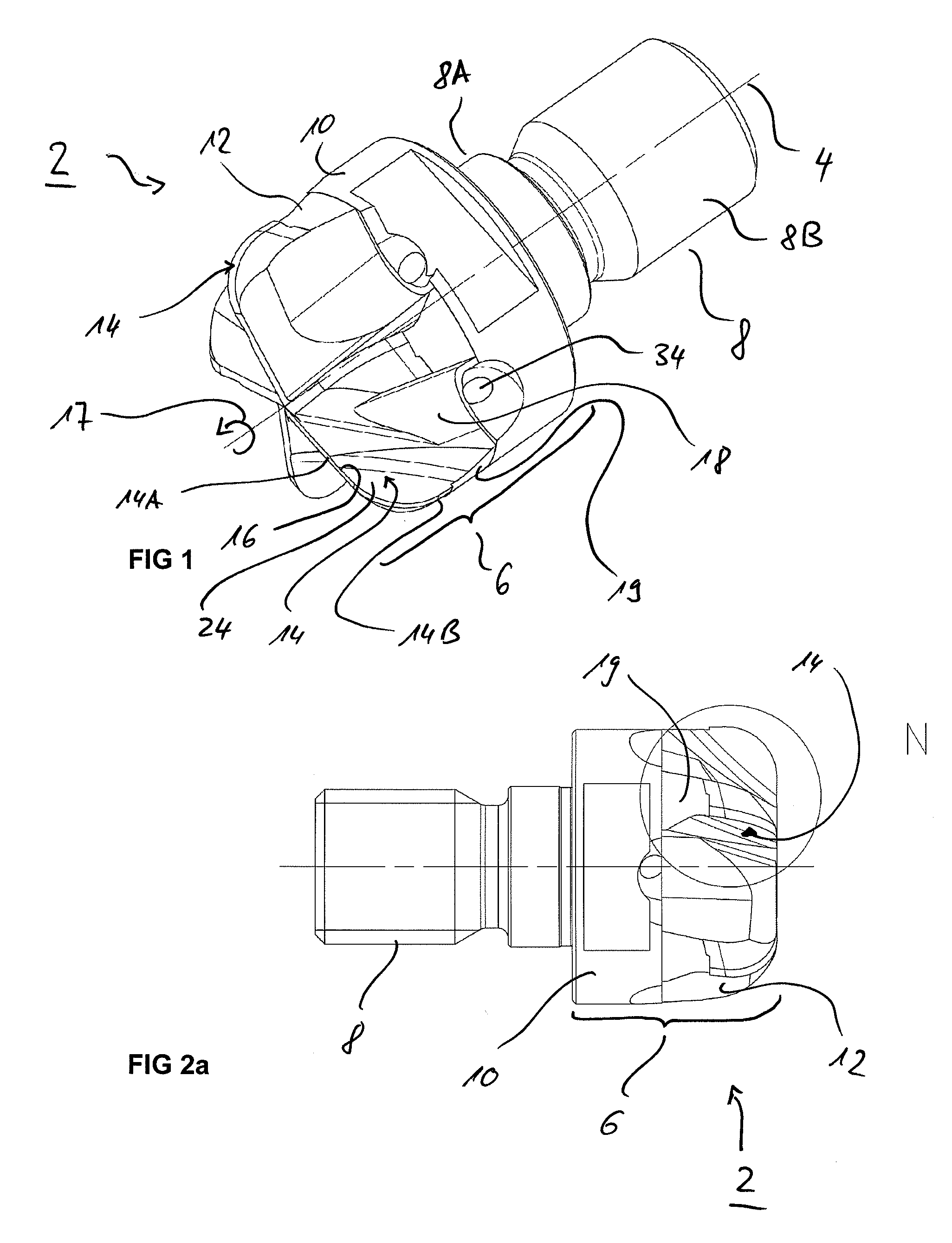
[0039]The milling cutter 2 represented in the figures is used generally to produce so-called “ball races”, in particular in the field of automobiles, to enable an articulated wheel suspension to be achieved. The milling cutter 2 as a whole extends in the axial direction 4, and has a tool head 6 and, adjoining the latter, a clamping shank 8. The clamping shank 8 is used to clamp the milling cutter 2 in a tool holder 9 (cf. FIG. 5). At its front end, the clamping shank 8 has an adapter collar or guide collar 8A and, at its rear end, it has a draw-in bolt 8A. Clamping in this case is understood to mean any fastening, for example a fastening in the manner of a bayonet lock, but also, in particular, fastening by screwing in.

[0040]In the exemplary embodiment, the tool head 6 is realized in two parts, being a carrier part 10 and a cutting part 12 fastened thereon, in particular by hard-soldering. ...


PUM


Abstract

The milling cutter, in particular a round-head milling cutter, has a tool head, which extends along an axial direction and has a number of cutting teeth that each have a cutting edge. Chip flutes are located between each of the cutting teeth. The cutting teeth each have a front-side radial portion and a circumferential axial portion. The respective cutting edge and the chip flute are disposed such that they are inclined in opposite directions with respect to the axial direction such that the cutting tooth widens towards a foot region. In another embodiment, the tool head has two parts; a carrier part made of a tool steel, and a cutting part made of hard metal fastened to the carrier part. The milling cutter is distinguished by a long service life with a high cutting rate and a high quality of machining.

Description

BACKGROUND OF THE INVENTION[0001]1. Field of the Invention[0002]The invention relates to a milling cutter having the features of the preamble of claim 1, and of the preamble of claim 9.[0003]2. Description of Related Art[0004]Such milling cutters, in particular round-head milling cutters, are known, for example, from WO 2008 / 116446 A1 and DE 697 29 945 T2.[0005]In the present case, round-head milling cutters, also known as ball milling cutters, are understood generally to mean those shank milling cutters that have a tool head comprising a number of cutting teeth that each comprise a cutting edge. The respective cutting edge in these cases first runs radially outward, approximately in the radial direction, in a front-side radial portion of the respective cutting tooth, and passes, via an arcuate course, into a circumferential axial portion of the cutting tooth extending substantially in the axial direction. A ball milling cutter in the narrower sense is understood in this case to mea...

Claims


Application Information

Patent Timeline
IPC IPC(8): B23C5/02B23C5/28
CPCB23C5/10B23C5/28B23C2210/02B23C2210/03Y10T407/1946B23C2210/0485B23C2210/204B23C2240/08Y10T407/1962B23C2210/0442B23C2210/405B23C5/283
Inventor HOBOHM, UWEMANNER, HEINRICH GEORGZITZMANN, WERNER
Owner KENNAMETAL INC
Why Eureka
Try Eureka