Ultrasonic atomizing method and ultrasonic atomizing device

An ultrasonic wave and atomizer technology, applied in the field of ultrasonic atomization methods and ultrasonic atomizers, can solve the problem of increased fouling of the ultrasonic transducer 2, limiting the installation direction of the atomization generator 1 or the ultrasonic transducer 2, and inability to Issues such as self-flow

Inactive Publication Date: 2007-04-18
KERI ELECTRONICS GUICHENG NANHAI CITY
View PDF2 Cites 9 Cited by
  • Summary
  • Abstract
  • Description
  • Claims
  • Application Information

AI Technical Summary

Problems solved by technology

[0005] 1. Since the plane of the ultrasonic transducer 2 can only be installed and used substantially parallel to the liquid surface of the liquid, the installation direction of the atomization generator 1 or the ultrasonic transducer 2 is limited
[0006] 2. Since the ultrasonic transducer 2 is sunken in the bottom of the pit formed in the sealing device, even if the atomization generator 1 has stopped working and the li

Method used


Image

  • Ultrasonic atomizing method and ultrasonic atomizing device
  • Ultrasonic atomizing method and ultrasonic atomizing device
  • Ultrasonic atomizing method and ultrasonic atomizing device

Examples


Embodiment 1

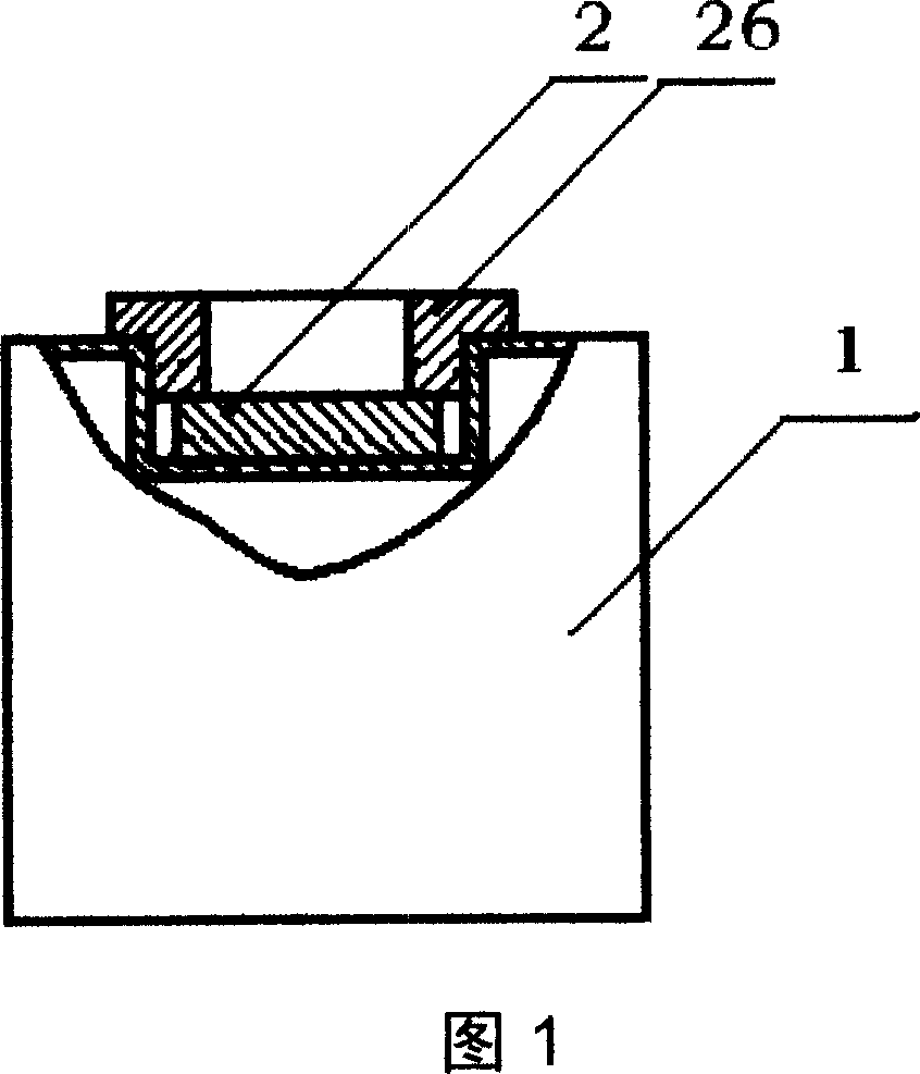
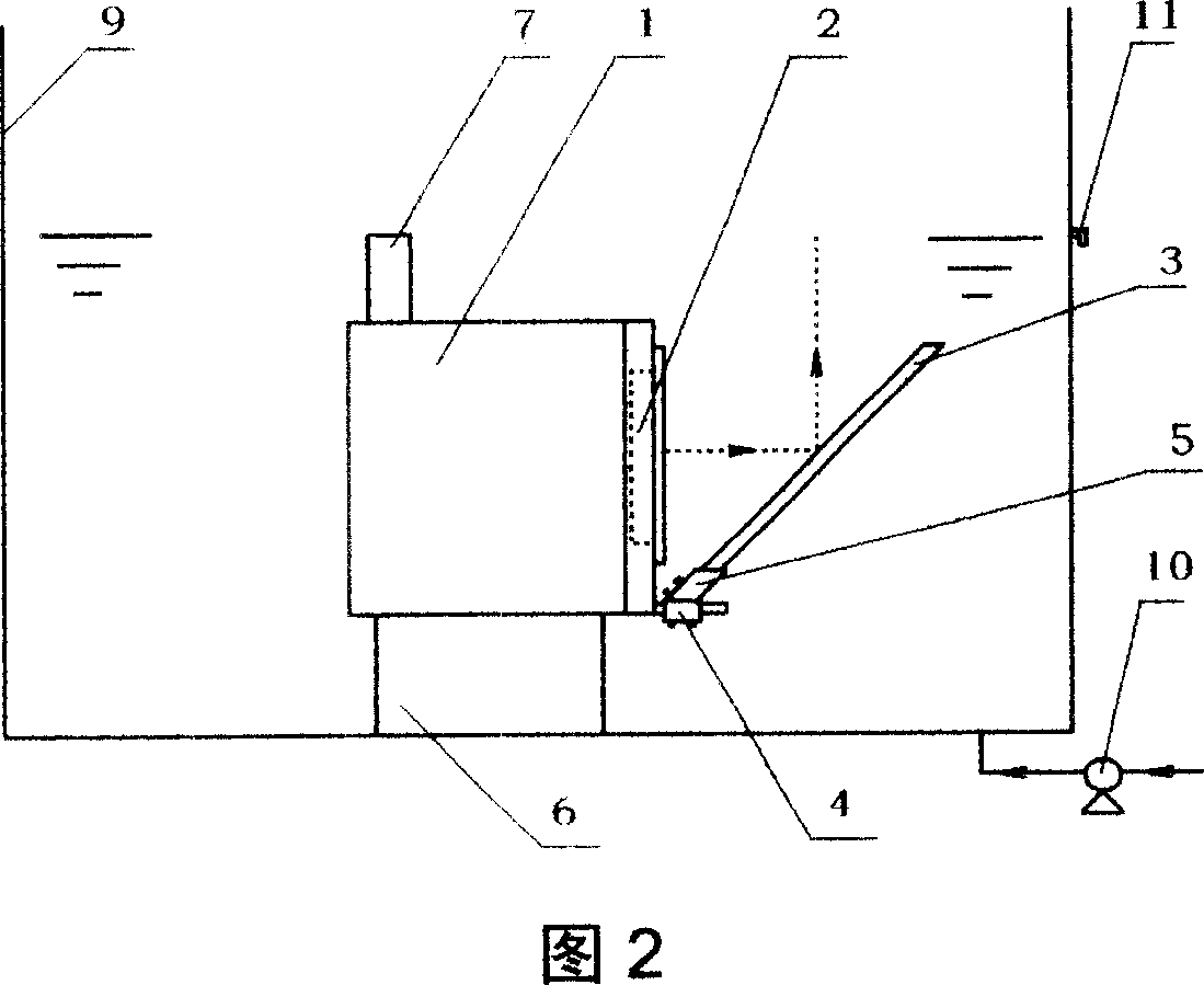
[0047] Embodiment 1: As shown in Figure 2, the atomization generator 1 is a square, and a first ultrasonic transducer sheet 2 is arranged on one side of the side shell of the atomization generator 1; The front of the first ultrasonic transducer sheet 2 is also provided with an upwardly inclined flat first reflector 3; The plane of the ultrasonic transducer 2 is at an angle of 45 degrees, so that the cavitation bubble can be flushed out perpendicular to the liquid surface; the lower part of the first reflection plate 3 is provided with a first displacement regulator 4 and a first angle regulator 5; The first reflection plate 3, the first displacement regulator 4 and the first angle regulator 5 are connected as one, and connected with the bottom of the atomization generator 1, placed on the platform 6 in the liquid container 9; the atomization generator 1 The upper part of the casing is provided with a water level detector 7; the bottom of the liquid container 9 is provided with...

Embodiment 2

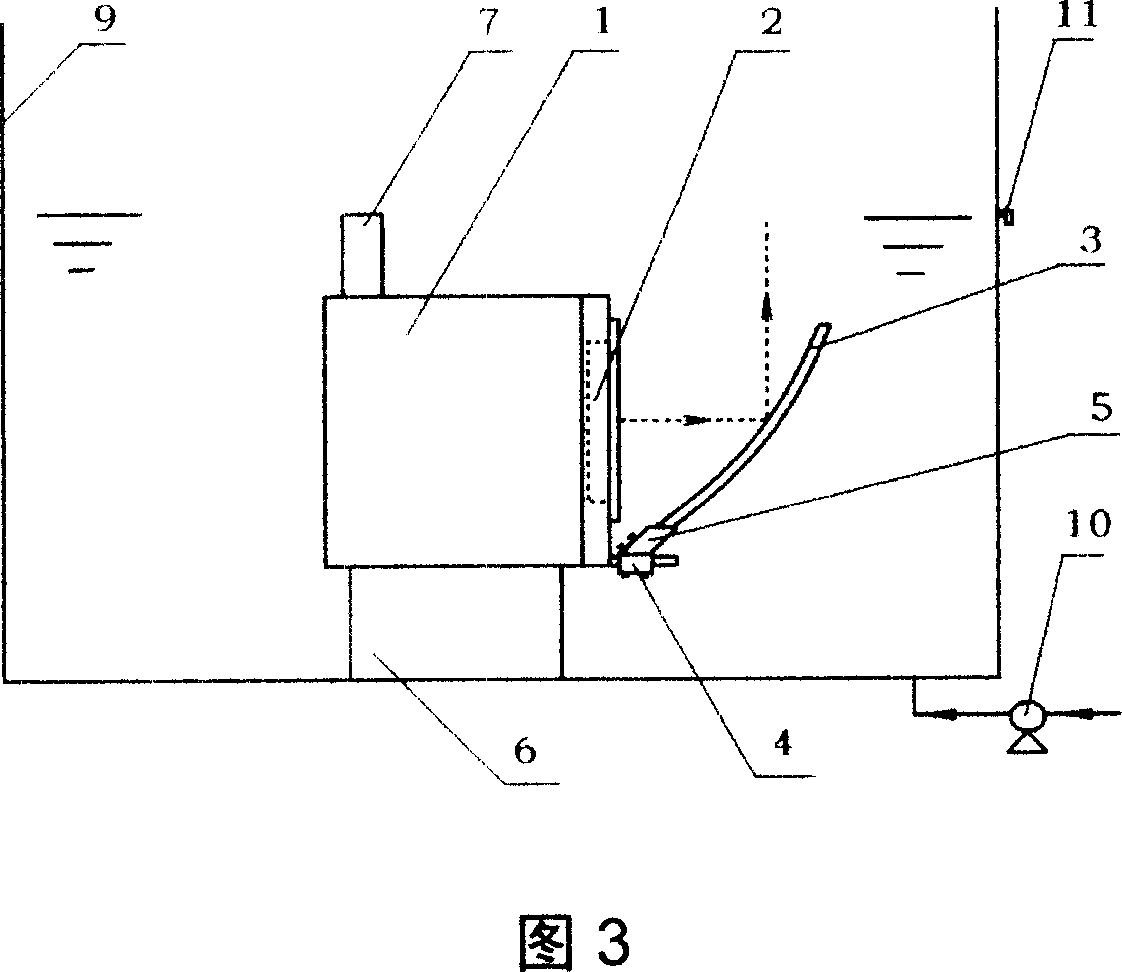
[0048] Embodiment 2: As shown in FIG. 3 , on the basis of Embodiment 1, the upwardly inclined flat plate-shaped first reflector 3 arranged directly in front of the first ultrasonic transducer sheet 2 is arranged to be upwardly inclined The other structures and connections are the same as those in Embodiment 1.

Embodiment 3

[0049] Embodiment three: as shown in FIG. 4, on the basis of embodiment one, a second ultrasonic transducer sheet 22 is set on the other side opposite to the side where the first ultrasonic transducer sheet 2 is located, and the second ultrasonic transducer sheet 22 is set. The front of the transducer sheet 22 is also provided with an upwardly inclined second reflector 33; the angle between the plane of the second ultrasonic transducer sheet 22 and the liquid surface is 60 degrees, and the plane of the second reflector sheet 33 and the second ultrasonic transducer sheet 22 planes form an angle of 60 degrees, so that cavitation bubbles can be flushed out in a direction perpendicular to the liquid surface; the second reflector 33 is provided with a second displacement regulator 44 and a second angle regulator 55; the first reflector 3. The first displacement adjuster 4 and the first angle adjuster 5 are integrated and arranged on the platform 6; the second reflector 33, the secon...


PUM


Abstract

An ultrasonic atomizer with high antiscaling effect, high atomizing efficiency, and multiple installation directions is composed of an atomizer, an ultrasonic transducer arranged on the casing of atomizer, and an inclined reflecting plate in the front of ultrasonic transducer. It features that the surface of ultrasonic transducer can be put in liquid by a certain angle to prevent dirt deposition.

Description

technical field [0001] The invention relates to an ultrasonic atomization method and the technical field of an ultrasonic atomizer. Background technique [0002] Ultrasonic nebulizers use mechanical energy to atomize liquids such as water and pharmaceuticals to achieve the purpose of disinfection, viewing or humidifying the environment. [0003] In the prior art, such as Chinese Patent No. CN95210144.0, authorized announcement date August 7, 1996, titled "Integrated Ultrasonic Nebulizer", and Chinese Patent No. CN02227244.3, authorized announcement date March 2003 On the 12th, titled "An Ultrasonic Atomizing Humidifier", a single-head ultrasonic atomizer and a multi-head ultrasonic atomizer were disclosed. [0004] The single-head ultrasonic atomizer of the prior art is still a multi-head ultrasonic atomizer. As shown in FIG. To prevent the liquid from penetrating into the atomizer 1 and damaging the control circuit components. The ultrasonic transducer sheet 2 is recesse...

Claims


Application Information

Patent Timeline
IPC IPC(8): B05B17/06
Inventor 余志英
Owner KERI ELECTRONICS GUICHENG NANHAI CITY
Why Eureka
Try Eureka