

Energy-storage stapler
A stapler and energy storage technology, which is applied in the field of staplers, can solve the problems of complex structure, inconvenient portability, and large volume, and achieve the effects of improving the efficiency of staples, being convenient to carry, and compact in structure
- Summary
- Abstract
- Description
- Claims
- Application Information
AI Technical Summary
Problems solved by technology
Method used
Image


Examples
Embodiment 1
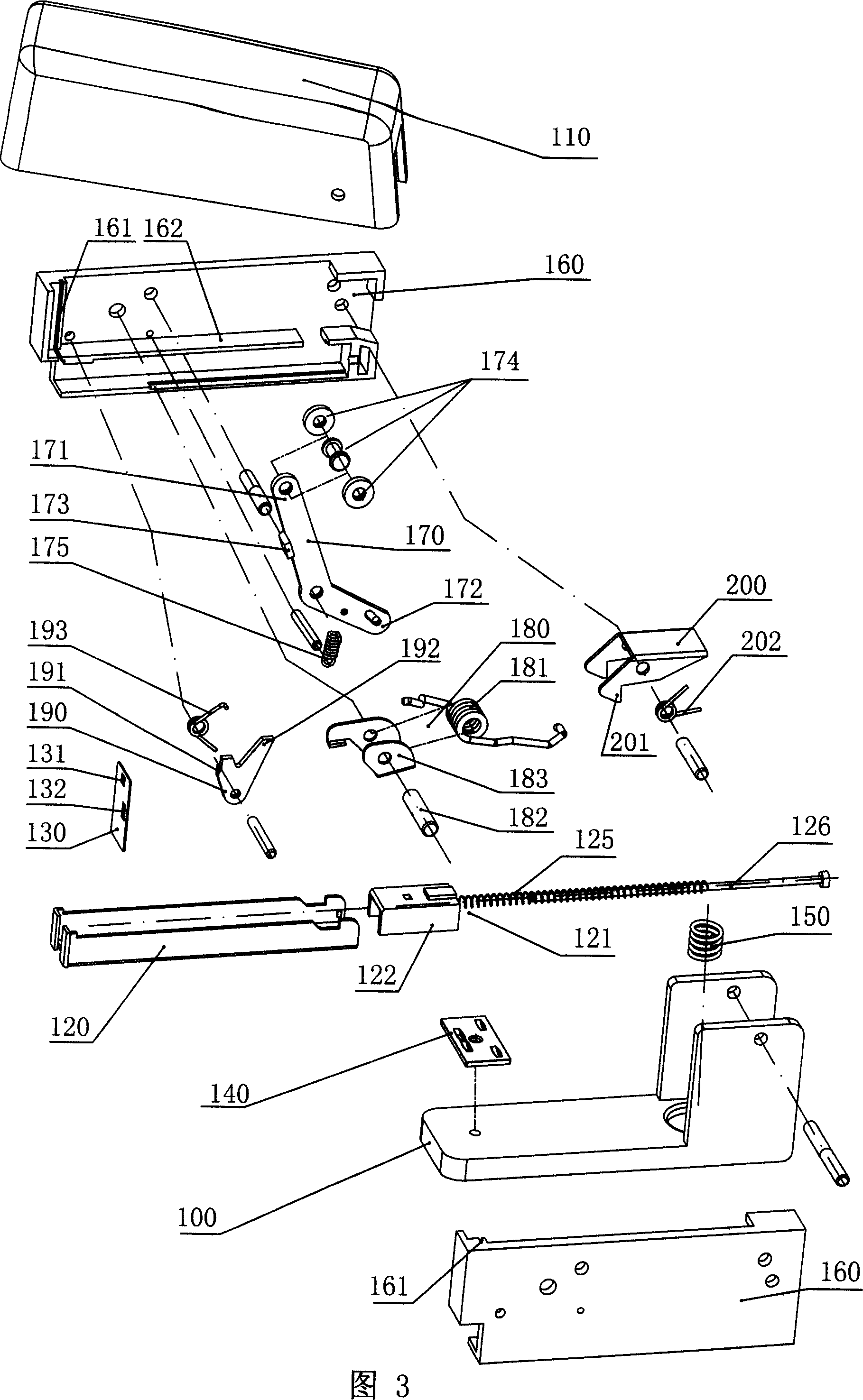
[0037] Figure 3 shows a three-dimensional schematic diagram of the dismantled structure of Embodiment 1 of the present invention; Figures 4, 5, and 6 respectively show the three moments of loading, pressing, and pressing in the operation process of Embodiment 1 of the present invention A cross-sectional schematic diagram of the assembled structure.
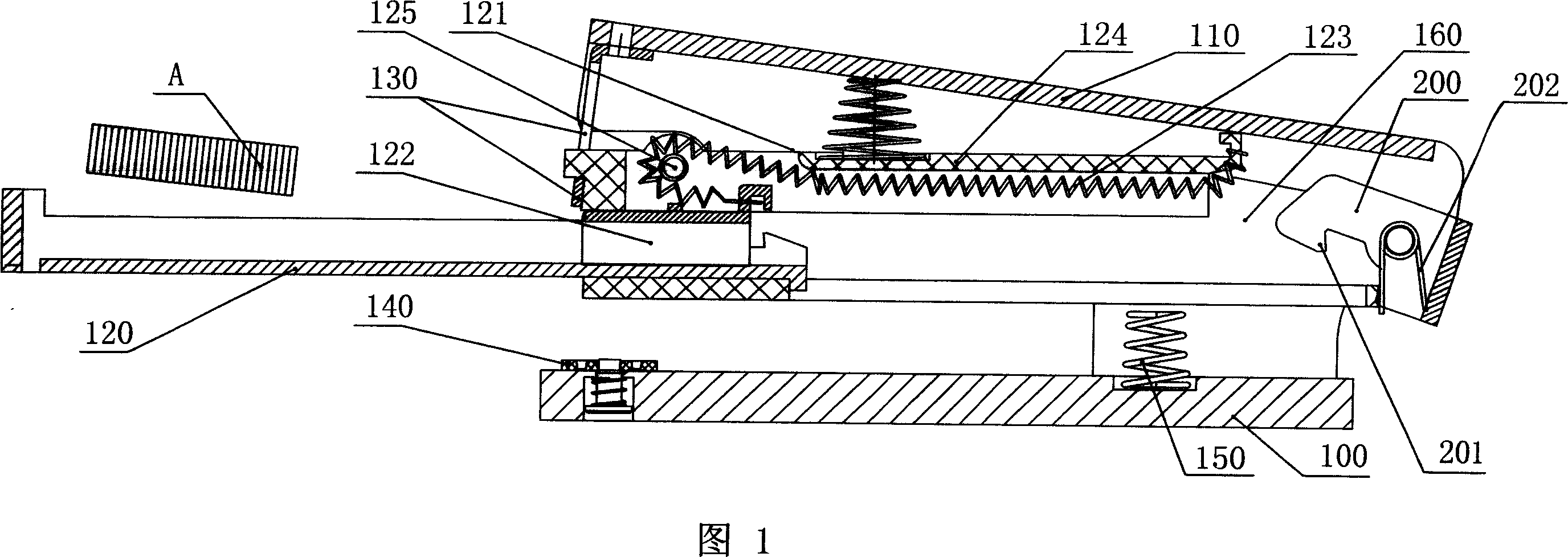
[0038]Embodiment 1 of the energy storage type stapler of the present invention includes a base 100, an upper cover 110, a staple groove 120 and a staple piece 130 for pressing the staple A in the staple groove, and the staple groove 120 is slidably fitted with The elastic needle pusher 121 , the elastic needle pusher 121 includes a compression spring 125 , a needle pusher piece 122 , and a guide shaft 126 fitted in the middle of the compression spring 125 .
[0039] On the base 100 , a needle plate 140 is arranged at the position corresponding to the falling of the nail sheet 130 , and the needle plate 140 is horizontally hinged o...
Embodiment 2
[0049] Figures 7, 8, and 9 are schematic cross-sectional views of the assembly structure at three moments of book needle loading, pressing, and needle pressing in Embodiment 2 of the present invention, respectively.
[0050] Embodiment 2 of the energy storage type stapler of the present invention includes a base 100, an upper cover 110, a staple groove 120, and a staple piece 130 for pressing the staples in the staple groove, and the sliding fit in the staple groove 120 is elastic. The needle pusher 121 is provided with a needle plate 140 on the base 100 at a position corresponding to the falling of the nail plate 130 , and the needle plate 140 is horizontally hinged on the base 100 . A bottom spring 150 is also provided on the base 100 .
[0051] Except for the spring energy storage device, the structure of all its components is the same or similar to that of Embodiment 1, and will not be repeated here.
[0052] And its spring energy storage device 180 comprises an elastic e...
Embodiment 3
[0058] As shown in Figure 10, it is a three-dimensional schematic diagram of the assembly of the main structure of Embodiment 3 of the present invention (the upper cover is removed); as shown in Figures 11, 12, and 13, respectively, the book-loading needles, Schematic cross-sectional view of the assembly structure at three moments of pressing and pressing.
[0059] Embodiment 3 of the energy storage type stapler of the present invention includes a base 100, an upper cover 110, a staple groove 120, and a staple piece 130 for pressing the staples in the staple groove, and the sliding fit in the staple groove 120 is elastic. The needle pusher 121 is provided with a needle plate 140 on the base 100 at a position corresponding to the falling of the nail plate 130 , and the needle plate 140 is horizontally hinged on the base 100 . A bottom spring 150 is also provided on the base 100 .
[0060] Except for the spring energy storage device 180, all its components are the same or simil...
PUM
 Abstract
Description
Claims
Application Information