Floor drain having waste hot water rocovery mouthpiece

A waste hot water and floor drain technology, applied in the field of floor drains, can solve the problems of increased environmental pollution, large discharge of domestic waste hot water, waste of energy, etc., and achieve the effects of energy saving, good economic and social benefits, and reduction of thermal pollution

Inactive Publication Date: 2007-04-18
HANGZHOU DIANZI UNIV
View PDF0 Cites 9 Cited by
  • Summary
  • Abstract
  • Description
  • Claims
  • Application Information

AI Technical Summary

Problems solved by technology

[0002] With the improvement of people's living standards, the consumption of daily hot water is increasing year by year, and almost all of the domestic hot water is discharged directly after use. Relevant statistics show that the average temperature of domestic waste hot water is about 32°C, which is very good. In addition, my country is a country with a large population, and the total discharge of domestic waste hot water is very large. Direct discharge of this waste water with a large amount of heat energy will not only waste energy, but also increase environmental pollution.

Method used


Image

  • Floor drain having waste hot water rocovery mouthpiece
  • Floor drain having waste hot water rocovery mouthpiece

Examples


Embodiment 1

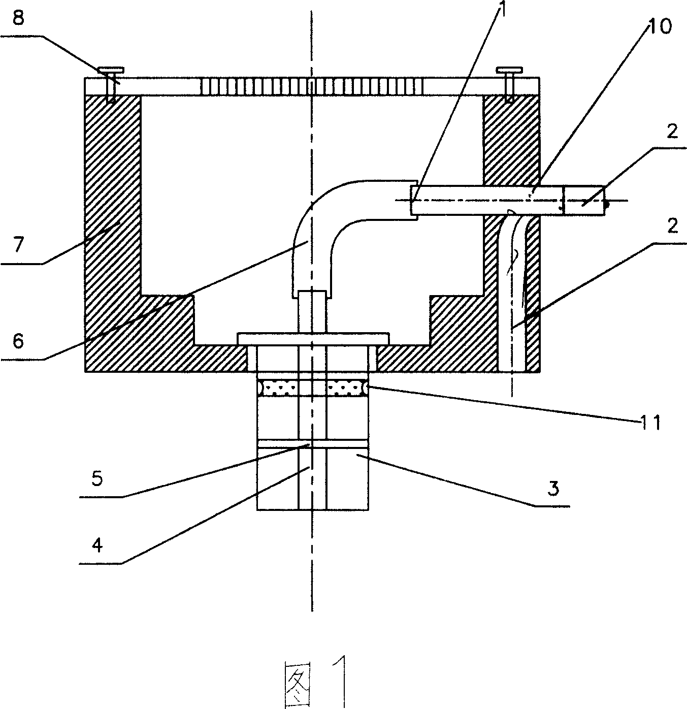
[0012] As shown in Figure 1, a floor drain with a waste hot water recovery interface described in this embodiment is mainly composed of a floor drain body 7, a cover plate 8, a waste hot water extraction channel 1, a waste hot water transition chamber 3, and a filter screen 5 The waste hot water transition chamber 3 is arranged at the bottom of the floor drain main body 7, the nozzle of the water suction pipe 4 of the waste water hot water extraction passage 1 is arranged at the bottom of the waste water hot water transition chamber 3, and the water intake pipe 10 of the waste water hot water extraction passage 1 passes through the floor drain main body 7 Leading to the outside, the filter screen 5 is set on the waste hot water transition chamber 3, the cover plate 8 is connected to the floor drain main body 7, the upper part of the waste water hot water transition chamber 3 is provided with an overflow hole 11, and the floor drain main body 7 is provided with a waste water drai...

Embodiment 2

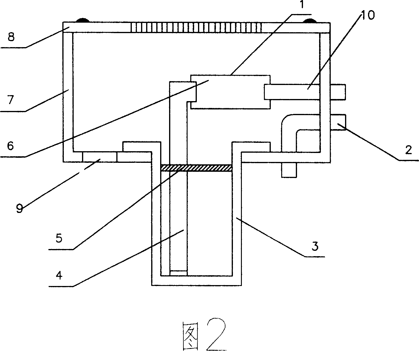
[0016] As shown in FIG. 2 , this embodiment describes a floor drain with a waste water recovery interface, and the floor drain main body 7 is made of thin-walled metal material. There are two through-hole structures on its surface, which are respectively used to install the waste hot water extraction passage 1 and the drainage channel 2. An overflow hole 9 is provided on the floor drain main body 7. The waste hot water transition chamber 3 is set on the steps of the floor drain main body 7. The water suction pipe 4 is socketed with the filter screen 5 as a filter and a water intake interface functional part. As shown in FIG. 2 , the drainage channel 2 is realized by setting a pipeline channel outside the wall of the floor drain main body, and is installed on the floor drain main body 7 . The waste hot water extraction channel 1 is composed of a water suction pipe 4, a hose 6 and a water intake connection 10, and the drainage channel 2 passes through the floor drain main body 7...


PUM


Abstract

This invention discloses a floor drain with the waste water recycling interface. It mainly consists of the floor drain, the cover board, the waste heat water extraction path, the waste heat water transition cavity and the strainer. The waste water transition cavity is set in the bottom of the floor drain, the suction duct mouth waste heat water extraction path is set in the bottom of the waste heat water transition cavity which the water intake pipe is connected to the outside though the floor drain. The strainer is set on the waste water transition cavity, the cover board covers on the floor drain. The floor drain with the waste water recycling interface matched with the heat exchanger can use the heat energy in the waste heat water, so it can save energy for the family and decrease the heat pollution to the environment and has the good economic and social benefits.

Description

technical field [0001] The invention relates to a floor drain, in particular to a floor drain with a waste hot water recovery interface. Background technique [0002] With the improvement of people's living standards, the consumption of daily hot water is increasing year by year, and almost all of the domestic hot water is discharged directly after use. Relevant statistics show that the average temperature of domestic waste hot water is about 32°C, which is very good. In addition, my country is a country with a large population, and the total discharge of domestic waste hot water is very large. Direct discharge of this waste water with a large amount of heat energy will not only waste energy, but also increase environmental pollution. Contents of the invention [0003] The purpose of the present invention is to solve the shortcomings of the above-mentioned technologies and provide a waste water recovery interface with a waste water recovery interface that can extract waste ...

Claims


Application Information

Patent Timeline
Patent Type & Authority Applications(China)
IPC IPC(8): E03C1/282F24J3/00
Inventor 丁强姜周曙
Owner HANGZHOU DIANZI UNIV
Why Eureka
Try Eureka