
Pump structure

A motor and central technology, which is applied in the field of drive pump structure, can solve the problems such as the inability to improve the liquid cooling effect, the limitation of the maximum water output, and the fixed water output.

Inactive Publication Date: 2007-04-18
TATUNG COMPANY
View PDF0 Cites 2 Cited by
  • Summary
  • Abstract
  • Description
  • Claims
  • Application Information

AI Technical Summary

Problems solved by technology

The water output of the pump driven by liquid cooling is limited to the traditional maximum water output, and the water output is fixed, so the liquid cooling effect cannot be improved relatively.
On the other hand, the power W loss of the 12VDC brushless DC servo motor is larger than that of the new technology, and the power consumption increases

Method used


Image

  • Pump structure
  • Pump structure
  • Pump structure

Examples


Embodiment Construction

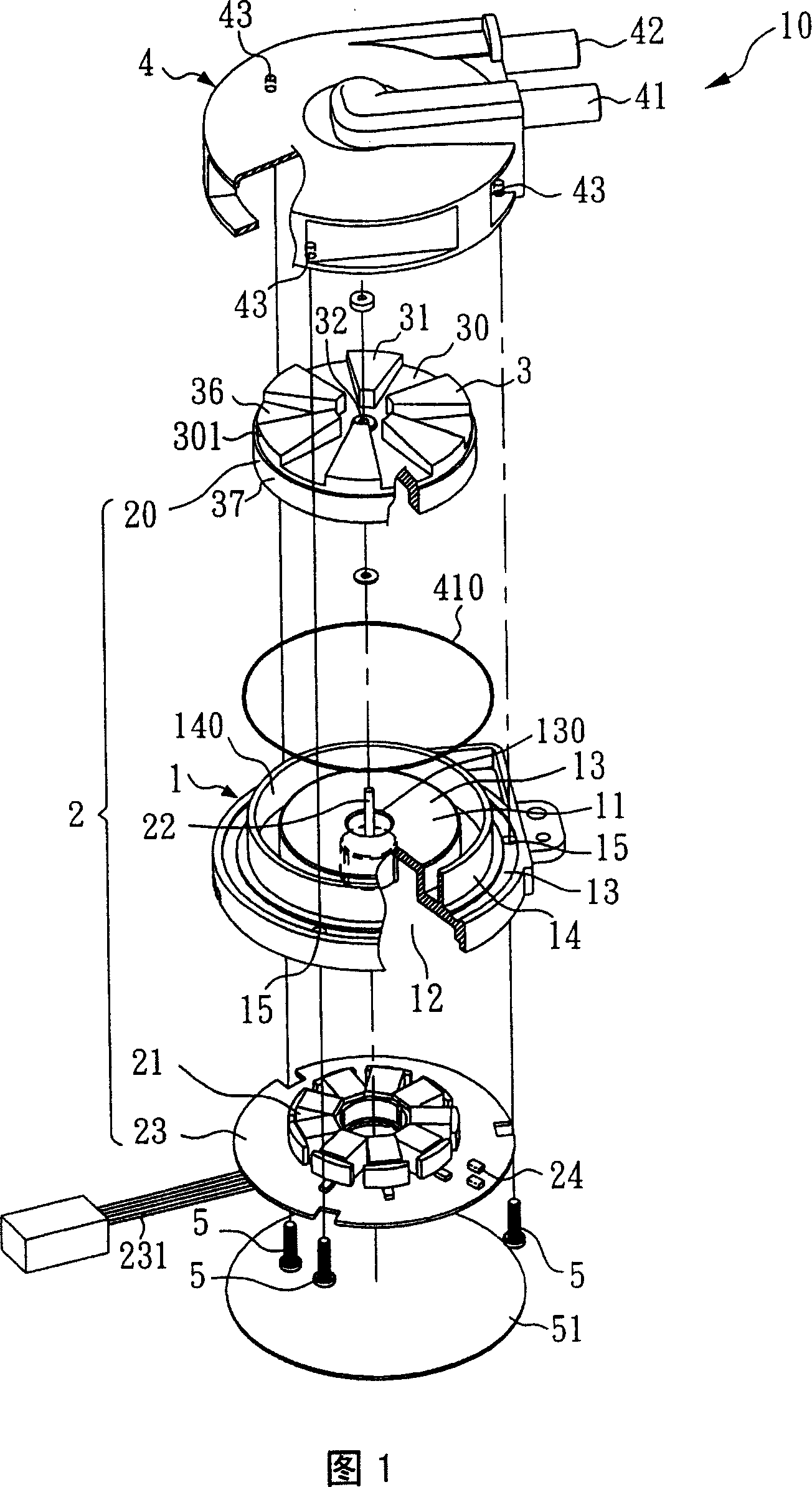
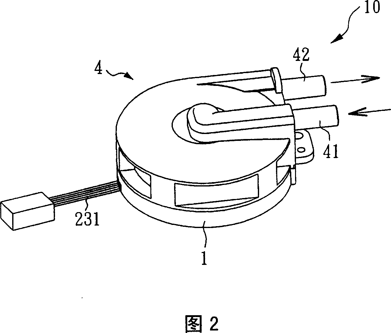
[0024] Please refer to FIG. 1, which is an exploded view of a preferred embodiment of the present invention. As shown in the figure, a pump structure 10 includes a base 1, a motor 2, a central pivot 22, a pump blade 3, and a Upper cover 4.

[0025] In this embodiment, the base 1 protrudes upwards with a convex portion 11, and the convex portion 11 includes an upper surface 13, a lower groove 12, and a central opening 130, wherein the central opening 130 communicates with the upper surface 13 and Lower groove 12.

[0026] In addition, an annular wall 14 protrudes from the upper surface 13 of the base 1, and an oil seal 410 is sheathed on the annular wall 14. In this embodiment, the oil seal 410 uses an O-ring. At the same time, the annular wall 14 and the The protrusions 11 are spaced apart from each other and form an accommodating chamber 140 .

[0027] The motor 2 in the accompanying drawing is a DC brushless three-wire servo motor 2 using 5VDC, including a rotor 20, a stat...


PUM


Abstract

The inventive pump structure comprises a base, a motor, pump vanes and a top cap. The pump vanes are disposed on the base and sleeved on the rotation shaft of the motor. On top of the pump vanes are disposed several fan-shaped blades and each fan-shaped blade has the same area with each other. On each fan-shaped blade are formed several indentation regions and each indentation region has the same area with each other. The area of each indentation region is the same as the area of each fan-shaped blade, thus, after the liquid flows in, by using the motor drives the pump vanes to rotate, the liquid is extruded and then ejected from the outlet because of the centrifugal force.

Description

technical field [0001] The invention relates to a pump structure, in particular to a driving pump structure suitable for a liquid cooling unit. Background technique [0002] Previously used in liquid cooling devices such as D / T PC or Server computer CPU radiators, the liquid cooling drive pump used was a twelve-volt direct current (12VDC) DC brushless servo-controlled motor. [0003] In addition, the above-mentioned drive pump structure uses a scroll blade and is equipped with a 12VDC DC brushless servo motor. Due to the scroll blade design of the known technology, a 12VDC DC brushless servo motor is used to drive the scroll blade to rotate. The water output of the pump driven by liquid cooling is limited to the traditional maximum water output, and the water output is fixed, so the liquid cooling effect cannot be improved. On the other hand, the power W loss of the 12VDC brushless DC servo motor is larger than that of the new technology, and the power consumption increases...

Claims


Application Information

Patent Timeline
IPC IPC(8): F04D13/06
Inventor 王坤仪
Owner TATUNG COMPANY
Features
  • Generate Ideas
  • Intellectual Property
  • Life Sciences
  • Materials
  • Tech Scout
  • Unparalleled Data Quality
  • Higher Quality Content
  • 60% Fewer Hallucinations
Learn More