
Electric machine

A bearing chamber and ball bearing technology, applied in electrical components, electromechanical devices, electric components, etc., can solve the problems of inconsistent axial installation position of the circlip, vibration and noise, and ball bearing shaking.

Inactive Publication Date: 2007-04-18
常州美能特机电制造有限公司
View PDF0 Cites 5 Cited by
  • Summary
  • Abstract
  • Description
  • Claims
  • Application Information

AI Technical Summary

Problems solved by technology

The ball bearings of the existing motors are generally installed in the metal end cover by screw riveting technology. The disadvantage of this structure is that the axial installation position of the elastic retaining ring is not consistent, and the force is not consistent when the screw is riveted, causing the elastic retaining ring to press the ball bearing. big or small
If the force is too large, the adjustment effect of the ball bearing is not good, and the resistance of the motor is large; if the force is small, the ball bearing shakes, the support is unstable, and it will cause vibration and noise
In addition, the existing structure also has the disadvantage of high manufacturing cost

Method used


Image

  • Electric machine
  • Electric machine
  • Electric machine

Examples


Embodiment Construction

[0010] The present invention is described in further detail below in conjunction with the embodiment that accompanying drawing provides.

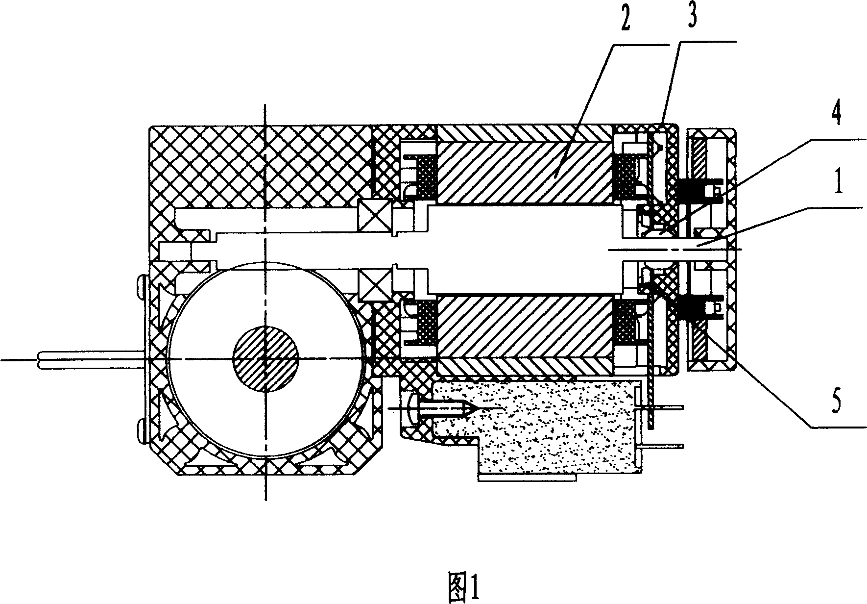
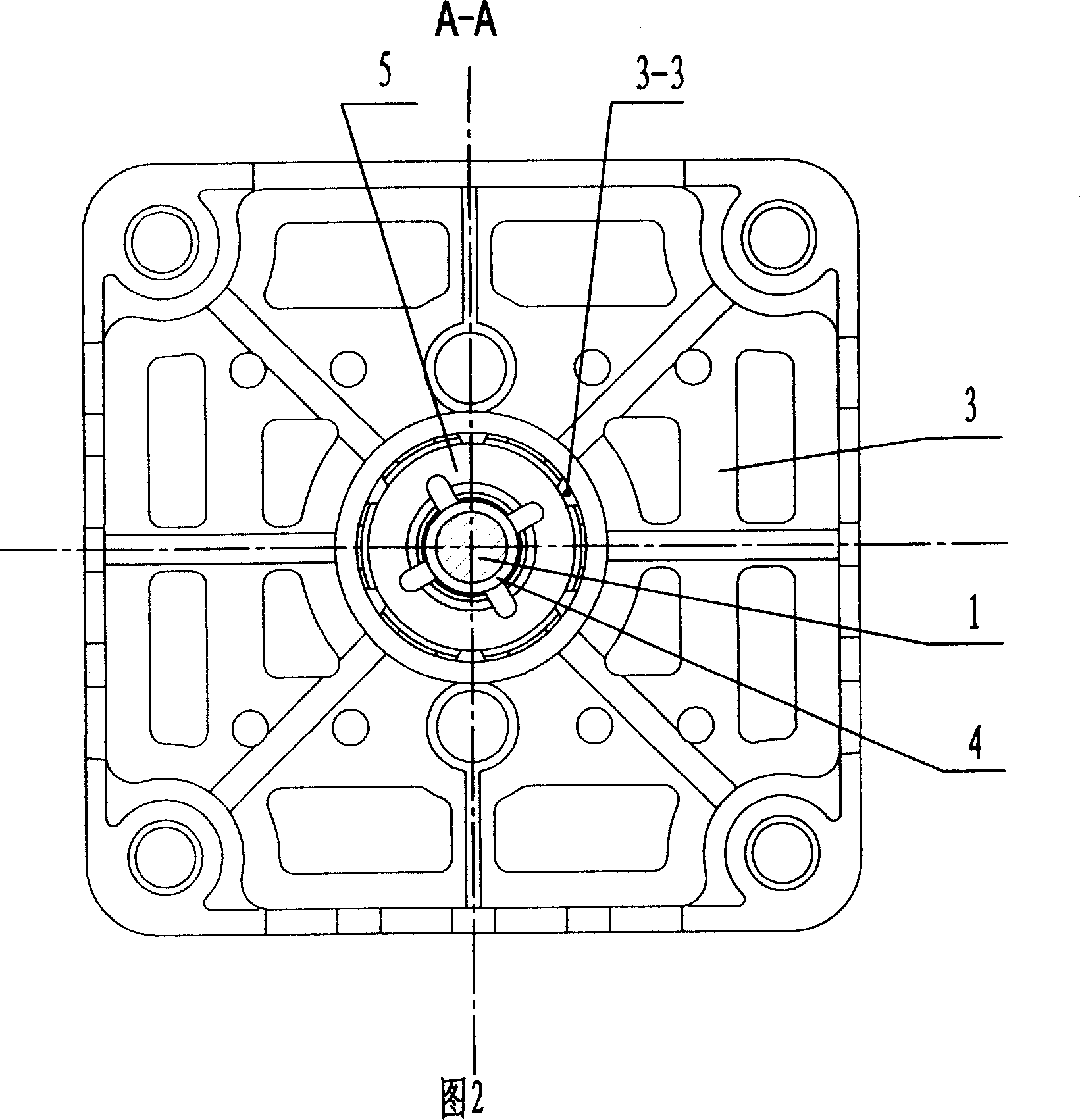
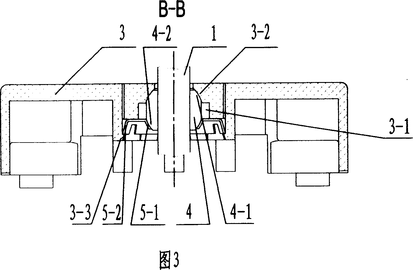
[0011] As shown in Figures 1 to 4, the motor of the present invention includes a stator 2, a rotor shaft 1 and an end cover 3, the end cover 3 is provided with a bearing chamber 3-1, and a ball bearing 4 is housed in the bearing chamber 3-1, and the rotor shaft At least one end of 1 is supported in the ball bearing 4, the inner wall of the bearing chamber 3-1 has an inner spherical surface 3-2 in contact with one side of the spherical surface 4-1 of the ball bearing 4, and the inlet end of the bearing chamber 3-1 is snapped elastically The retaining ring 5, the elastic retaining ring 5 has an inner spherical surface 5-1 in contact with the other spherical surface 4-2 of the ball bearing 4.

[0012] As shown in Figures 2, 3, and 4, the inlet end of the bearing chamber 3-1 is provided with several barbs 3-3, and the elastic retaining ring 5 h...


PUM


Abstract

The invention discloses a motor, comprising stator, rotor shaft and end cover, where the end cover is equipped with bearing room, a ball bearing is arranged in the bearing room, at least one end of the rotor shaft is supported in the ball bearing, the inner wall of the bearing room has an inner spherical surface contacting a side spherical surface of the ball bearing, the inlet end of the bearing room is fastened with an elastic shield ring, the elastic shield ring has an inner spherical surface contacting the other side spherical surface of the ball bearing. And it can make the pressure of the elastic shield ring to the bearing meet the design requirements, unable to cause higher or lower pressure phenomenon and convenient to manufacture and low-cost.

Description

technical field [0001] The invention relates to a motor, in particular to the structure of the motor. Background technique [0002] The end cover on the motor is usually equipped with a ball bearing. The main function of the ball bearing is to adjust the concentricity of the rotor shaft by using the adjustment function of the ball bearing when the two mounting holes of the front and rear end covers of the motor are not completely concentric. the goal of. The ball bearings of the existing motors are generally installed in the metal end cover by screw riveting technology. The disadvantage of this structure is that the axial installation position of the elastic retaining ring is not consistent, and the force is not consistent when the screw is riveted, causing the elastic retaining ring to press the ball bearing. power is greater or lesser. If the power is high, the adjustment effect of the ball bearing is not good, and the resistance of the motor is large; if the power is sm...

Claims


Application Information

Patent Timeline
IPC IPC(8): H02K5/16H02K5/173
Inventor 龚家雄殷明龚晓骏
Owner 常州美能特机电制造有限公司
Learn More